Creative Cedar Designs Jungle Fun 3201 Owner'S Manual And Assembly Instructions Download Page 5

The instructions and owner’s manual for your new Playcenter should be read in its 

entirety before assembly, to minimize problems and safety issues.  We recommend

reading the owner’s manual thoroughly after you have identified all of the parts for your 

Playcenter as discussed in the Helpful Installations Hints section below. 

Positioning Your Play center 

1. The Playcenter is designed to be installed on a level surface

by an Adult with an Adult 

helper

.  Try to place in a flat area of your yard to minimize ground preparation.

2. Choose a level location for the equipment.  This can reduce the likelihood of the play set 

tipping over and loose-fill surfacing material washing away during heavy rains. 

3. Place the equipment not less than 6 ft from any structure or obstruction such as a fence, 

garage, house, overhanging branches, laundry lines, or electrical wires. 

4. Provide enough room so that the children can use the equipment safely. For example, for 

structures with multiple play activities, a slide should not exit in front of a swing. 

5. It is a good idea to place your Playcenter in an area that is convenient for adults to watch 

children at play.

6. Create a site free of obstacles that could cause injuries – such as low overhanging tree 

branches, overhead wires, tree stumps and/or roots, large rocks, bricks and concrete. We 

have additional suggestions in the Suggested Playground Surfacing Section. 

7. Do not build your playset on top of surfacing material. 

8. Locate bare metal platforms and slides out of direct sunlight to reduce the likelihood of 

serious burns.  A slide that faces north will receive the least direct sunlight. 

9.

Separate active and quiet activities from each other.  For example, locate sandboxes away

from swings or use a guardrail or barrier to separate the sandbox from the movement of 

the swings.


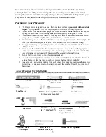
Tools Required for Installation: 

(These are the tools that are generally required for assembly of our playsets. These tools are not included in the playset purchase.)

An Adult w/an

Adult helper


Ladder

3

Open End Wrenches

(7/16” & 1/2”)

Level 24”

Nut Drivers

(1/2” & 9/16”)

3/8” Drive Ratchet, (1/2” & 9/16”) 

Std Socket & Deep Well

Tape Measure

Claw Hammer

Screw Drivers

(Phillips & Straight)

Rubber Mallet (Optional)

3/8” Drill

Drill Bits - 6” long

(1/8”,  5/16” & 3/8”)

Drill attachments

(3/8” Socket Driver

Torque head screw)

Summary of Contents for Jungle Fun 3201

Page 1: ...Model 3201 Jungle Fun SGS COC 005310 1996 Forest Stewardship Council A C For FSC certified products look for the FSC label Follow the Sequoia plans thru phase 23 then proceed with these instructions...

Page 2: ...sitioning Your Playcenter 3 Tools Required for Assembly 3 Helpful Installation Hints 4 Suggested Playground Surfacing 5 Operating Instructions 6 Maintenance Instructions 7 Disposal Instructions 7 CPSC...

Page 3: ...HELP WITH WHAT YOU NEED For more efficient service please log onto our website at www creativecedardesigns com and fill out a request for missing or damaged parts A completed product registration is...

Page 4: ...n your installation continued satisfaction and safe operation of your Creative Cedar Designs purchase Always keep the safety of your children in mind as your play structure is being built and as your...

Page 5: ...idea to place your Playcenter in an area that is convenient for adults to watch children at play 6 Create a site free of obstacles that could cause injuries such as low overhanging tree branches over...

Page 6: ...you understand more clearly the installation process and help to eliminate unnecessary mistakes 7 Pay close attention to the diameter and length of each bolt and screw 8 Swing hangers should be burie...

Page 7: ...Standard Specification of Impact Attenuation of Surfacing Materials within the Use Zone of Playground Equipment The following chart explains the fall height in feet from which a life threatening head...

Page 8: ...to sit in the center of the swings with their full weight on the seats 9 Instruct children not to use the equipment in a manner other than intended 10 Instruct children to always go down slides feet f...

Page 9: ...parts 6 For rusted areas on metallic members such as monkey bars hand supports brackets etc sand and repaint using a non lead based paint meeting the requirements of Title 16 CRF Part 1303 7 Inspect w...

Page 10: ...ecause children may deliberately jump from a moving swing the shock absorbing material should extend in the front and rear of a swing a minimum distance of 2 times the height of the pivot point measur...

Page 11: ...may present a choking hazard to small children Please keep these bags and all plastic bags out of the reach of children Do no allow children to play with them and dispose of them immediately when emp...

Page 12: ...h phase thoroughly The written steps may include important information not shown in the illustrations 4 Pay close attention to the Items needed and Hardware needed sections of each phase They can be a...

Page 13: ...RIDGE H PF3819 1 1 X 5 X 25 BRIDGE I PF3818 1 1 X 5 X 24 1 2 BRIDGE J PF3817 1 1 X 5 X 24 BRIDGE K PF3816 6 1 X 3 5 8 X 24 STEPS PF3815 2 1 X 3 1 2 X 49 3 8 BASE LONG PF3808 2 1 X 3 1 2 X 27 STEP FRON...

Page 14: ...Accessories 26 BRIDGE SPACERS P301 4 FENCE STAPLE H 8 CABLE CLAMP O2 1 BRIDGE CABLE O1 1 BRIDGE SUPPORT STRAP M301 2 ROPE RAILING Q 12 Parts Identification Wooden Bridge g 4 GREEN L BRACKET M002...

Page 15: ...oc Nut 5 16LN 5 16 x 1 1 2 Lag Bolt L 8 1 Do not include bolt head when measuring length of bolt NOTES 2 Include full length of deck screw when measuring 1 4 1 1 2 3 4 2 3 4 5 6 It is very important t...

Page 16: ...T 1 x 3 1 2 x 49 3 8 BASE LONG 1 x 3 5 8 x 24 STEPS 1 x 5 x 24 BRIDGE K 1 x 5 x 24 1 2 BRIDGE J 1 x 5 x 25 BRIDGE I 1 x 5 x 25 1 2 BRIDGE H 1 x 5 x 26 BRIDGE G 1 x 5 x 26 1 2 BRIDGE F 1 x 5 x 27 BRIDG...

Page 17: ...hase 25 SLIDE ATTACHMENT 15 POSITION SLIDE CENTERED IN AN OPENING AND 4 INTO THE TOWER AS SHOWN INSTALL 4 TRUSS SCREWS PER SLIDE LARGE WAVE SLIDE GREEN Phase Parts Phase Hardware 1 Truss Head Screw S...

Page 18: ...shown in STEP 1 2 Attach Step Support boards as shown in STEP 2 3 Attach Bridge Platform Step boards as shown in STEP 3 4 Attach Step Support boards as shown in STEP 4 PF3830 8 3 8 PF3805 PF3837 PF38...

Page 19: ...pe Railing Support boards as shown in STEP 2 3 Attach Bridge Cable Support board as shown in STEP 3 4 Attach Bridge Platform Angle Support boards as shown in STEP 4 20 COUNTER BORE S FACING THIS SIDE...

Page 20: ...BRIDGE ASSEMBLY STEP 2 STEP 1 63 1 2 GAP PF 3829 8 2 1 2 DECK SCREWS Rope Railing Support must be plumb and level Assemble Bridge Platform cont HOLE DETAIL 1 Attach Top Step boards as shown in STEP 1...

Page 21: ...Z3259 BRIDGE SUPPORT WZ3259 BRIDGE SUPPORT LD203 UPRIGHT LD203 UPRIGHT LM226 WALL RAIL LM219 END FLOOR SUPPORT 2 3 1 2 LAG SCREWS BOTH SIDES 2 5 16 FLAT WASHERS STEP 1 1 MARK TWO HOLES ON UPRIGHTS AS...

Page 22: ...p 2 Mark and drill 4 5 16 holes thru upgrights 2 on each upright Step 3 Insert 4 5 16 T nuts into backside of uprights Step 4 Attach M301 Support Strap with 4 1 1 4 deck screws 4 5 16 X 3 1 4 Hex bolt...

Page 23: ...1 Phase 31 BRIDGE ASSEMBLY 5 16 x 6 DRILL BIT LD203 UPRIGHT 65 1 16 80 1 16 Bridge Tower Prep Rope Railing Step 1 Mark hole locations centered on uprights as shown Step 2 Drill 5 16 holes at locations...

Page 24: ...Eye bolt thru platform upright and secure with hardware as shown 3 Repeat steps for opposite side NOTE Space between upright and first rope Phase Hardware Phase Hardware K1 8 5 16 Flat Washer G1 8 5...

Page 25: ...ope Railing as shown below The cable will be routed starting from the left Tower side through the Bridge Boards Platform sturcture then back through the Bridge Boards as indicated by the arrows 1 1 X...

Page 26: ...le through left side of Bridge Boards as described in previous page Step 2 Thread cable through Platform down through the top across to the opposite side Step 3 Route cable through right side of Bridg...

Page 27: ...IDGE CLEAT PF3783 H 2 Fence Staple STEP 1 STEP 2 2 1 4 4 1 4 Assemble Bridge Secure Cable and Attach Cleats 1 Secure cable running underneath the Bridge Platform as shown in STEP 1 2 Attach Cleats as...

Page 28: ...rs STEP 1 Assemble Bridge Secure Cable and Attach tower 1 Thread Bridge Cable thru M301 Bracket WZ3259 Support as shown in STEP1 NOTE Deck boards are removed for clarity Bridge Spacers LD203 Bridge Ca...

Page 29: ...t and install Cable Clamp tight to WZ3259 Support 2 Install a fence staple above the Cable Clamp into WZ3259 Support for each cable as shown in STEP 1 3 Drill 3 8 hole s at location shown on uprights...

Page 30: ...CAP 5 16 LOCK NUT 5 16 FLAT WASHER EYE BOLT ASSEMBLY UNDER DECK VIEW LD203 TOP VIEW LM211 LM210 WZ3259 BRIDGE SUPPORT LM219 Assemble Bridge Finish and Secure Bridge 1 Thread cable through Eye Bolt and...

Page 31: ...ry board is secure Make sure playset is level SECURE PLAYSET 1 Place anchors at the locations shown 2 Twist the anchors into the ground until only the loop is exposed as shown 3 Place the metal strap...

Page 32: ...damaged by acts of God negligence misuse or accident or which have been modified or repaired by unauthorized persons b the cost of labor c the cost of shipping the product any part or any replacement...

Page 33: ...scription of the warranty issue 3 Photos of warranted parts and of the entire play system If any of the above steps are not completed there may be delays in the completion of your claim or possibly wa...

Page 34: ..._______________ City State Zip Code ___________________________________________________ Phone ________________________________________________________________ Date of Purchase ________________________...

Page 35: ...stration Card along with a copy of the receipt and return to Creative Cedar Designs within 30 days of original purchase in order to validate time of purchase for warranty FOLD HERE Place Stamp Here Cr...

Reviews: