30
Proprietary, patented product and assembly instructions. Do not copy or distribute.
LB Side 1
di
L
g
ni
wS
BL
te
kc
o
P
g
ni
wS
BL
Back Panel
RS1
S Base
RS2
RS2
S Base
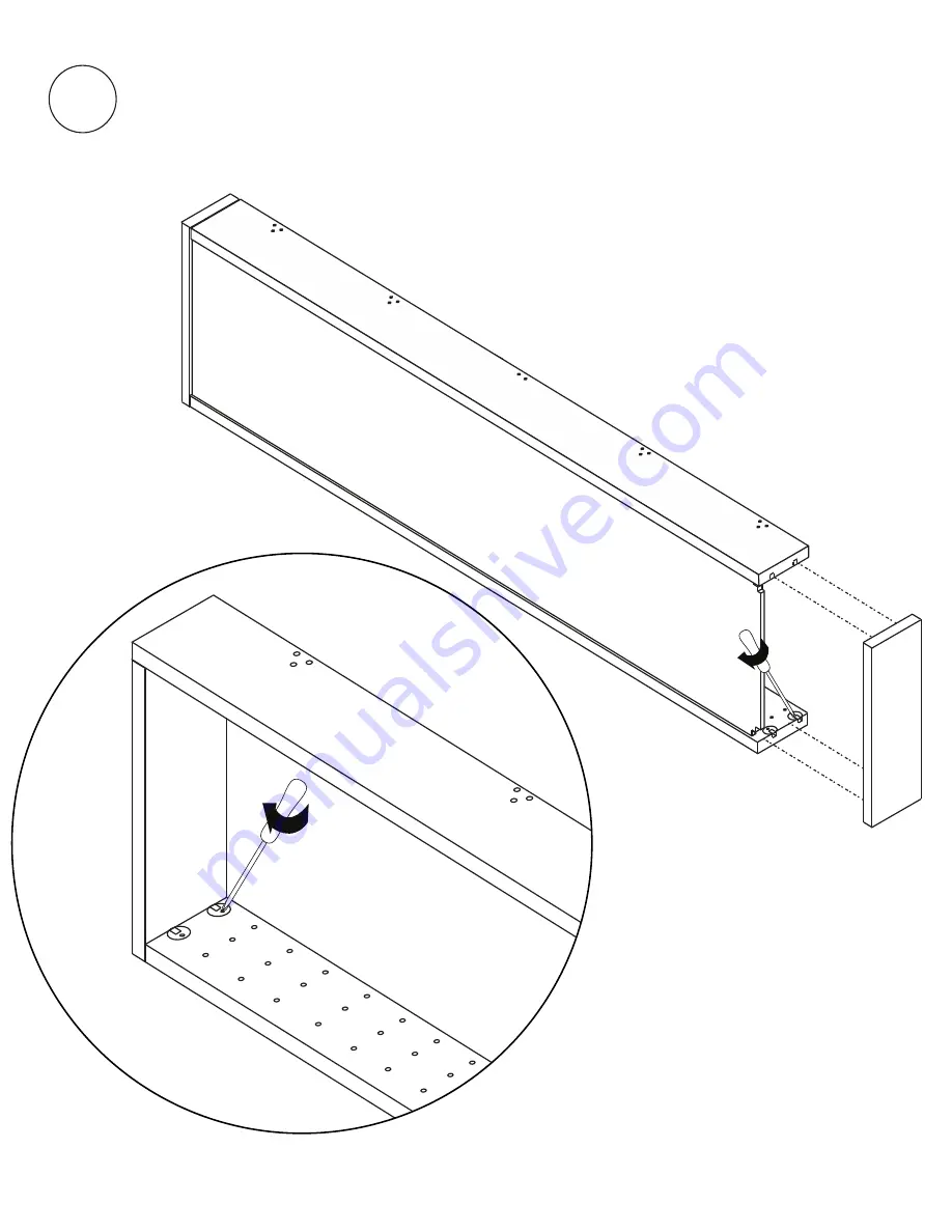
Attach S Base to RS1 and RS2 making
sure that Connecting Bolts and Locking
Cams are together. Tighten all 4 Locking
Cams.
6


