5
SECTION B: GENERAL INFORMATION
B-1) To the Purchaser:
Congratulations! You are the owner of one of the fi nest pumps
on the market today. These products are engineered and
manufactured of high quality components. Over one hundred
years of pump building experience along with a continuing
quality assurance program combine to produce a pump which
will stand up to the toughest applications.
This manual will provide helpful information concerning
installation, maintenance, and proper service guidelines.
B-2) Receiving:
Upon receiving the pump, it should be inspected for damage
or shortages. If damage has occurred, fi le a claim immediately
with the company that delivered the pump. If the manual is
removed from the packaging, do not lose or misplace.
B-3) Storage:
Short Term-
Pumps are manufactured for effi cient
performance following short inoperative periods in storage.
For best results, pumps can be retained in storage, as factory
assembled, in a dry atmosphere with constant temperatures
for up to six (6) months.
Long Term -
Any length of time exceeding six (6) months, but
not more than twenty-four (24) months. The units should be
stored in a temperature controlled area, a roofed over walled
enclosure that provides protection from the elements (rain,
snow, wind-blown dust, etc.), and whose temperature can be
maintained b40 deg. F and +120 deg. F.
If extended high humidity is expected to be a problem, all
exposed parts should be inspected before storage and all
surfaces that have the paint scratched, damaged, or worn
should be recoated with a water base, air dry enamel paint. All
surfaces should then be sprayed with a rust-inhibiting oil.
Pump should be stored in its original shipping container. On
initial start up, rotate impeller by hand to assure seal and
impeller rotate freely.
B-4) Service Centers
:
For the location of the nearest Prosser Service Center, check with
your Prosser representative or Crane Pumps & Systems, Inc.,
Service Department in Piqua, Ohio, telephone (937) 778-8947. or
Crane Pumps & Systems Canada, Inc., Bramton, Ontario,
(905) 457-6223
SECTION C: INSTALLATION
C-1) Location:
These pumping units are designed for use with hydraulic
systems in locations where electrical connections are
unavailable or hazardous. Before pumping fl uids other than
water, consult the factory, giving fl uid, fl uid temperature,
specifi c gravity, viscosity, capacity in USGPM and total head
and/or pressure requirements, including friction loss through
discharge line, fi ttings, valves, etc. Maximum fl uid temperature
for sustained operation is 140°F (60°C) at specifi c gravity 1.0.
Pump may operate up to 10 minutes running dry (not pumping
water) without damage. DO NOT allow pump to be buried in
mud or sand.
IMPORTANT ! - Pump should have strainer
affi xed at all times. Inspect and clean the pump
strainer periodically for maximum effi ciency and
performance.
C-2) Discharge:
Discharge hose is recommended. If rigid pipe is used, install
so that there is no weight or strain on the pump. Install a short
pipe nipple into the pump discharge to attach the discharge
hose above the hydraulic connections at the top of the pump.
Save and replace the plastic shipping plugs in the hydraulic
line connection at the top of the pump whenever the hydraulic
lines are disconnected. This is to protect against damage to
the connections and entrance of dirt.
C-3) Suction:
Completely submerge the suction strainer for maximum
pumping effi ciency. Avoid entrance of air into the suction of the
pump. Strainer should always be installed on the pump while
operating.
C-4) Liquid Level Controls:
(If Applicable)
Attach “ON” fl oat to discharge hose or pump cable at desired
pump “ON” level. Attach “OFF” fl oat to discharge hose or pump
cable at desired pump “OFF” level. The “OFF” fl oat must be
below the “ON” fl oat. To attach the fl oats, thread the cable
strap through the buckle with the ratchet pawl, cinch up tight,
thread excess strapping through outer buckle slot. Be certain
that the level controls cannot hang up or foul in its swing. It is
recommended that the pump is completely submerged when
the level control is in the “Off” mode.
C-5) Hydraulic System:
Figures 1 and 2 shows a schematic drawing of a typical
hydraulic power system for driving a submersible pump.
WARNING!- Hydraulic system has high-pressure
capability. Exercise caution at all times.
CAUTION ! - Never block return (low pressure)
line. It’s best to use by-pass valve to control fl ow
of hydraulic fl uid.
The 3HPV pump should be supplied with a maximum
hydraulic fl uid fl ow of 7 GPM @ 2500 PSI. Maintain hydraulic
fl uid temperature at 100°F (38°C) for optimum performance.
Maximum operating temperature is 180°F (82°C). Fluid
viscosity should be 214-320 SSU. An anti-wear hydraulic
fl uid of approximately 200 SSU at 100°F is recommended.
Lower viscosity fl uids can be used, but will increase the wear
rate within the hydraulic motor. A fi lter is required on the low
pressure return hydraulic fl uid line. Use fi lter elements rated
at 10 micron absolute. Protect hydraulic hoses from cuts and
abrasion. Always use a back-up wrench when connecting and
disconnecting the hydraulic lines to the fi ttings on top of the
pump.
Use hydraulic oils with anti-wear additives as listed or their
equivalent.
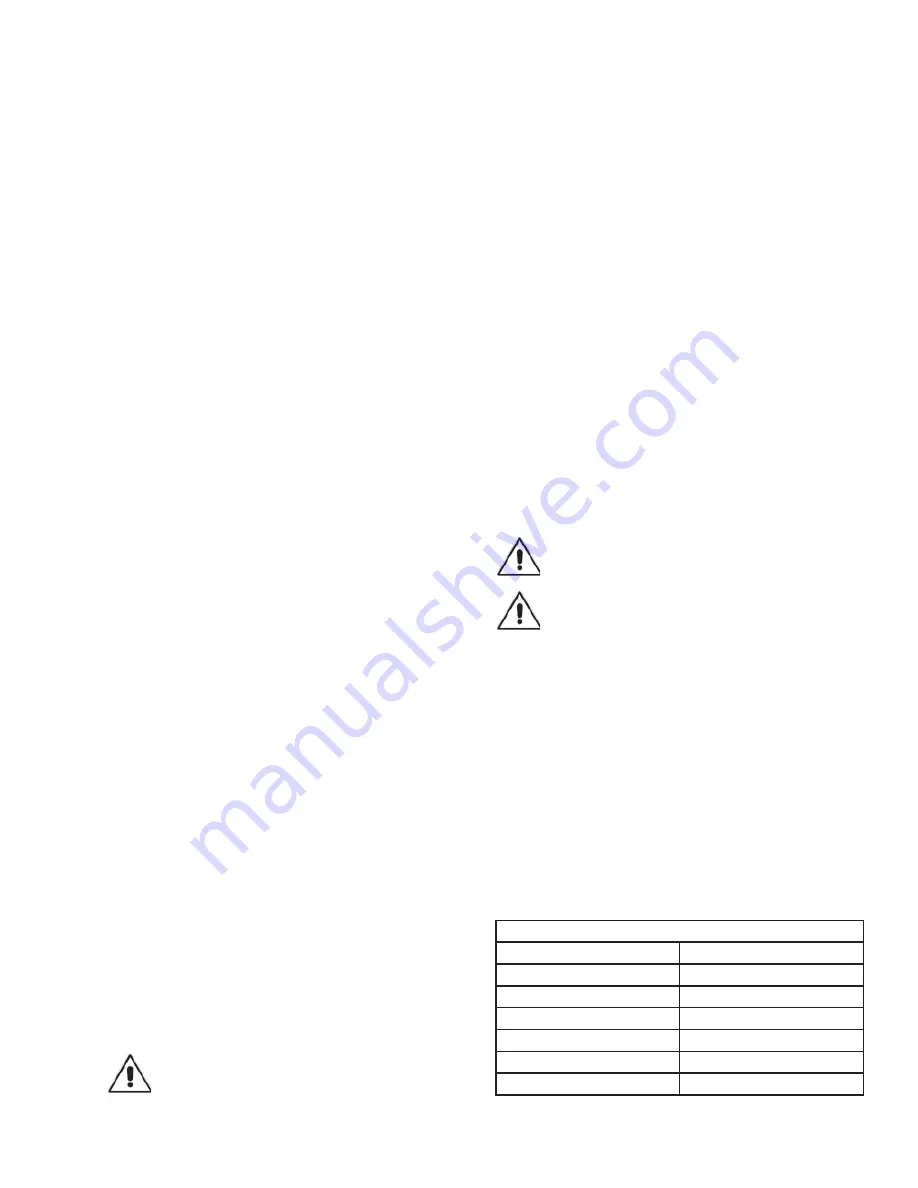
TABLE 1 - SEAL CHAMBER OIL
SUPPLIER
GRADE
Pennzoil
AW46 Hydraulic Oil
Texaco
Rando HDAZ
Shell
Tellas Hydraulic Oil
Mobil
D.T.E. 20 Series
Chevron
EP Hydraulic Oils
Exxon
J-58 Hydraulic Oil
Summary of Contents for Prosser Hymergible 3HPV
Page 10: ...10 FIGURE 3 ...
Page 14: ...14 Notes ...


