background image

8

BEFORE YOU BEGIN

• Read this manual completely before starting your 

   installation

• Consult local officials for any applicable codes and

  regulations.

• Make sure you have the necessary equipment and 

  supplies before starting your installation (see tool and

  material lists).

TOOL AND MATERIAL LIST 

(NOT INCLUDED)

• 1/2” Socket

• Ratchet

• Long Extension

• Wire Strippers (12 AWG to 18 AWG)

• Wire Cutters

• Multi-Meter

• Cable Lube

• Small Slotted Screw Driver

RECEIVING/UNPACKING:

Upon receiving the pump, it should be inspected for dam-

age or shortages. If damage has occurred, file a claim 

immediately with the company that delivered the pump. 

Unpack pump and record pump serial and model number 

before installing. If the manual is removed from the pack-

aging, do not lose or misplace.

STORAGE:

Short Term- 

For best results, pumps can be retained in 

storage, as factory assembled, in a dry atmosphere with 

constant temperatures for up to six (6) months.

Long Term-

 Any length of time exceeding six (6) months, 

but not more than twenty-four (24) months. The units 

should be stored in a temperature controlled area, a 

roofed over walled enclosure that provides protection 

from the elements (rain, snow, wind-blown dust, etc.), and 

whose temperature can be maintained b40 deg. 

F and +120 deg. F. If extended high humidity is expected 

to be a problem, all exposed parts should be inspected 

before storage and all surfaces that have the paint 

scratched, damaged, or worn should be recoated with a 

air dry enamel paint. All surfaces should then be sprayed 

with a rust-inhibiting oil.

Pump should be stored in its original shipping container. 

On initial start up, rotate impeller by hand to assure seal 

and impeller rotate freely. If it is required that the pump be 

installed and tested before the long term storage begins, 

such installation will be allowed provided:

1.)  The pump is not installed under water for more than


one (1) month.

2.)  Immediately upon satisfactory completion of the


test, the pump is removed, thoroughly dried, 


repacked in the original shipping container, and


placed in a temperature controlled storage area. 

SERVICE CENTERS:


For the location of the nearest Barnes Service Center, 

check your Barnes representative or

Crane Pumps & Systems, Inc., Service Department in 

Piqua, Ohio, telephone (937) 778-8947 or in Brampton, 

Ontario, Canada (905) 457-6223.
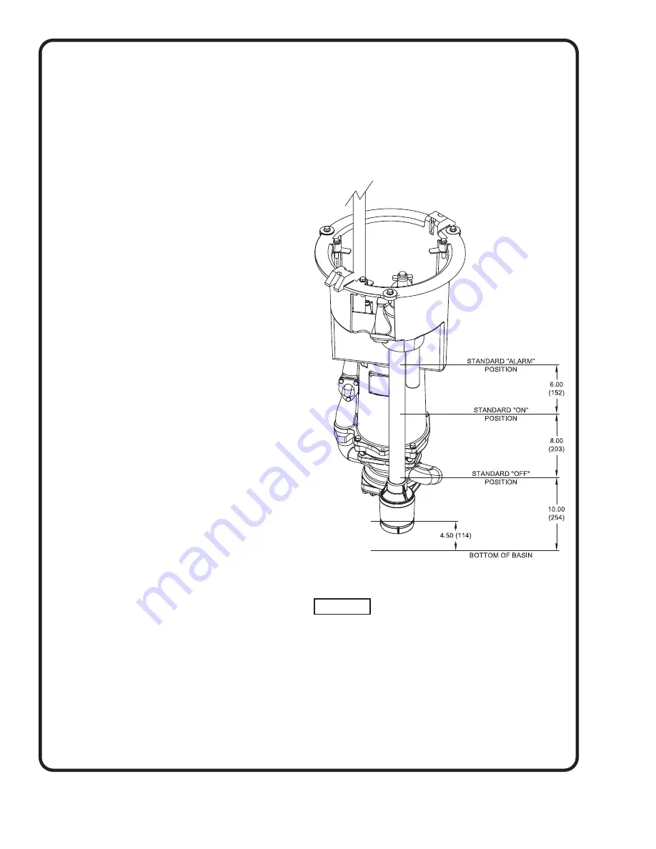
INSTALLATION:


Location -

 The pump is designed to fit into your basin 

suspended from the support pod.

Package Systems-

 Refer to manual supplied with basin 

package system.

FIGURE 1 

(Standard ESPS shown, SensaPRO optional)

Summary of Contents for OGP2022CO Series

Page 1: ...t 83 West Drive Bramton Piqua Ohio 45356 Ontario Canada L6T 2J6 Phone 937 778 8947 Phone 905 457 6223 Fax 937 773 7157 Fax 905 457 2650 www cranepumps com Form No 131783 Rev M Series OGP2022CO 2 HP 3450 RPM 60 Hz OGVH2022CO 2 HP 3450 RPM 60 Hz OGVF2022CO 2 HP 3450 RPM 60 Hz Fits into E One 200 2000 Series Basin Extreme D Series Basin This product may be covered by one or more of the following pate...

Page 2: ...R GUIDE 4 SPECIFICATIONS Fixed Discharge Upgrade Core 5 SPECIFICATIONS OGP Series 6 SPECIFICATIONS OGV Series 7 INSTALLATION 8 19 ELECTRICAL CONNECTIONS 9 16 LEVEL CONTROL INFO ESPS 150 17 19 LEVEL CONTROL INFO SensaPRO 19 EXPLODED VIEW Fixed Discharge Upgrade Core 20 PARTS LIST 21 EXPLODED VIEW OGP Series 22 PARTS LIST 23 EXPLODED VIEW OGV Series 24 PARTS LIST 25 DISCHARGE ASSEMBLY 26 WARRRANTY 2...

Page 3: ...before handling or servicing WARNING DO NOT pump hazardous materials flammable caustic etc unless the pump is specifically designed and designated to handle them WARNING DO NOT wear loose clothing that may become entangled in the impeller or other moving parts WARNING Keep clear of suction and discharge openings DO NOT insert fingers in pump with power connected Always wear appropriate safety gear...

Page 4: ...is the Barnes UltraGRIND grinder pump station The basin collects all wastewater from the house The solids in the sewage are then ground to a small size suitable for pumping in the slurry The grinder pump generates sufficient pressure to pump this slurry from your home to the wastewater plant Power Failure Your grinder pump cannot dispose of wastewater or provide an alarm signal without electrical ...

Page 5: ...or sealing and strain relief CORD CSA UL Approved 12 5 Type SOW SPEED 3450 RPM 60Hz UPPER BEARING Design Single Row Angular Contact Ball Lubrication Oil Load Radial Thrust LOWER BEARING Design Single Row Angular Contact Ball Lubrication Oil Load Radia Thrust MOTOR Design NEMA L Oil Filled Squirrel Cage Induction Insulation Class F SINGLE PHASE Capacitor start capacitor run SUPPORT POD Engineered P...

Page 6: ...2 240 1 H 16 5 53 8 12 5 SOW 71 15 5 15 4 6 1 06 3 60 Winding Resistance 5 measured from terminal block Pump rated for operation at 10 voltage at motor For 3 Phase models Temperature Sensor Cord is 14 3 SOW 0 55 14mm 02 51mm O D Recommended Breaker Sizes Pump Model HP Phase Volts Breaker Size OGP2022 2 1 240 25 AMP inches mm PUMP SPECIFICATIONS OGP OGP Threaded Shown ...

Page 7: ...53 8 12 3 SOW 61 15 5 1 5 5 1 OGVF2022CO 2 240 1 60 H 15 0 53 8 12 3 SOW 61 15 5 1 5 5 1 Winding Resistance 5 measured from terminal block Pump rated for operation at 10 voltage at motor Recommended Breaker Sizes Pump Model HP Phase Volts Breaker Size All OGV Series Pumps 2 1 240 25 AMP F for High Flow or H for High Head inches mm PUMP SPECIFICATIONS OGV OGV Threaded Shown ...

Page 8: ...w wind blown dust etc and whose temperature can be maintained between 40 deg F and 120 deg F If extended high humidity is expected to be a problem all exposed parts should be inspected before storage and all surfaces that have the paint scratched damaged or worn should be recoated with a air dry enamel paint All surfaces should then be sprayed with a rust inhibiting oil Pump should be stored in it...

Page 9: ... combined effect of temperature and current This means that the overload protector will trip out and shut the pump off if the windings become too hot or the load current becomes too high It will then automatically reset and start the pump after the motor cools to a safe temperature In the event of an overload the source of this condition should be determined and rectified immediately DO NOT LET TH...

Page 10: ... terminal block see Figures 4 5 Tighten bolts on compression flange until flush with motor housing Pump Power Large Pin Level Control Small Pin Level control cord has molded fitting at both ends of the cord Install one end to the Pump and the other end to the Level Control Standard ESPS shown SensaPRO optional FIGURE 5 FIGURE 4 ...

Page 11: ...ark on terminal block Use hardware provided to mount cord flange to pump Note that one connection has small pins and one as large pins Install the proper cord into the proper socket See Figure 4 Bowline knot lifting device rope to handles See Bowline knot detail See Figure 2 FIGURE 6 Standard ESPS shown SensaPRO optional ...

Page 12: ...plumbing as shown Be sure discharge piping assembly is fully engaged Next lower level control into basin with lifting rope aligning level control as shown Hang cords and ropes from existing hooks in tank Use zip ties provided as needed After unit and level control is lowered the valve handle will slide over piping assembly as shown FIGURE 7 Standard ESPS shown SensaPRO optional ...

Page 13: ...aker to control panel Ordered separately Rewire existing power supplied to control panel if required WIRE FEEDING THE PANEL NEEDS TO BE AT LEAST 12 GAUGE MAY NEED TO BE LARGER DEPENDING UPON LENGTH OF RUN CONSULT QUALIFIED ELECTRICIAN FOR PROPER APPLICATION Optional Cicuit Breakers Ordered Separately PART NO DESCRIPTION 113291B 20 AMP GE THQP Snap in Breaker 105476 20 AMP DIN Rail Breaker ...

Page 14: ...14 FIGURE 9 ...

Page 15: ...15 FIGURE 10 Wiring for units not supplied with Factory Installed EQD NOTE EQD 2000 Series shown EQD Extreme wired in same manner ...

Page 16: ...16 Wiring for Optional Remote Alarm Light FIGURE 11 ...

Page 17: ...be changed Any attempt to change the actuation points will void the warranty Before placing switch into service switch should be brought to operational temperature range Excessive or direct heating or cooling should NOT be used OPERATION TEMPERATURE RANGE 35 F 2 C to 120 F 49 C SHIPPING STORAGE TEMPERATURE 20 F 29 C to 150F 66 C FUNDAMENTALS OF OPERATION The ESPS 150E Level control is designed to ...

Page 18: ... ESPS 150E L1 G PUMP POWER CIRCUIT 115 230V 1PH WHT BLK BLK L2 MMP1 B1 G1 W1 ORG WHT PUMP 1 MOTOR WHT BLK WH BLK CB2 SR ORG ORG PRP WH ORG PRP 9 9 1 5 WHT ORG PRP W1 W1 X1 O1 R1 BLK BLK F1 3A RED BLK ORG WHT ORG BLU F2 3A ORG MMP1 9 1 BLU WH ORG N FIGURE 13 ...

Page 19: ...witch assembly from basin Step 2 REMOVING EXISTING LEVEL CONTROL POWER CABLE Disconnect level control power cable from ESPS Switch by removing two retaining screws and lock washers Step 3 INSPECTING EXISTING LEVEL CONTROL POWER CABLE Inspect level control power cable for damage on the cord jacket or pin connection areas Replace level control power cable if damage is found Step 4 ATTACH LEVEL CONTR...

Page 20: ...20 FIGURE 16 EXPLODED VIEW FIXED DISCHARGE UPGRADE CORE ...

Page 21: ...ESPS Cord Set 30 for ESPS 17 1 094270 Cord Grip 18 1 069054V Cord Grip 19 3 118954 Retaining Ring Nylon 20 1 118339 Grommet Black Nitrile 21 2 See BOM Rope Lift PP Dia 1 2 22 1 See BOM Rope ESPS Dia 1 4 3 Strands 23 1 133551 Serial Name Plate 25 1 055844 Connector Wire Not Shown 28 1 105714 Plug Not Shown 37 7 20 21 1 Washer 5 16 Passivated 38 1 131039 Support Pod PARTS LIST FIXED DISCHARGE UPGRAD...

Page 22: ...22 FIGURE 17 EXPLODED VIEW OGP SERIES ...

Page 23: ...Shown 29 1 116659 Ball Bearing Lower 30 1 or 2 625 02117 Sleeve 31 1 115327A Motor 2HP 240 Volt 1 Phase Includes items 26 thru 29 115327B Motor 2HP 240 Volt 1 Phase External Cap 125375 Motor 2HP 3PH OGP 50 60Hz 32 1 103760 Terminal Block Power Manual ITEM QTY PART NO DESCRITION 33 1 or 2 2 31051 224 O Ring 34 1 or 2 105197 Retaining Ring 36 14 1 156 1 Screw 5 16 18 x 1 00 SS 37 1 109498XC 109498 1...

Page 24: ...24 FIGURE 18 EXPLODED VIEW OGV SERIES ...

Page 25: ... Ball Bearing Lower 30 1 113287 Wiring Harnes Automatic 31 1 108368A Motor 2HP 240 Volt 1 Phase w capacitors Ground wire Supplied with Upper Bearing 31A 1 115327A RC Capacitor Run 31B 1 115327A SC Capacitor Start 31C 1 105111B Ground wire 31D 1 016660 Screw Self Tap 8 32 x 31 31E 6 039462 Cable tie strap 34 1 103760 Terminal Block Power Manual ITEM QTY PART NO DESCRITION 35 1 or 2 2 31051 224 O Ri...

Page 26: ...t 4 1 124538 Lower Guide Bracket 5 2 027113 HXHD Screw 5 16 18 x 875 6 3 or 5 026322 Lock Washer 5 16 SS 7C 1 118794 Valve Body 8 1 625 01558 O Ring 223 1 609 9 1 119854 Diaphragm 10 1 118248 Diaphragm Retaining Plate 11 8 118267 FHHS Screw 10 32 x 75 SS 12 3 2 23030 50 SkHd Screw 5 16 18 x 1 25 The Discharge Assembly will be factory assembled to pump ...

Page 27: ...Notes ...

Page 28: ...Notes ...

Page 29: ...A RETURNED GOODS AUTHORIZATION CONTACT YOUR LOCAL CRANE PUMPS SYSTEMS INC DISTRIBUTOR Products Returned Must Be Cleaned Sanitized Or Decontaminated As Necessary Prior To Shipment To Insure That Employees Will Not Be Exposed To Health Hazards In Handling Said Material All Applicable Laws And Regulations Shall Apply IMPORTANT WARRANTY REGISTRATION Your product is covered by the enclosed Warranty If ...

Reviews: