background image

3

Please Read This Before Installing Or Operating Pump. 
This information is provided for 

SAFETY

 and to 

PREVENT 

EQUIPMENT PROBLEMS.

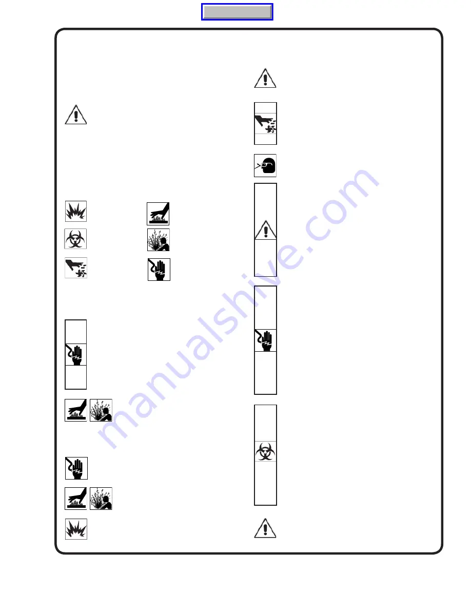
 To help recognize this information, 

observe the following symbols:

IMPORTANT!

 Warns about hazards that can result 

in personal injury orIndicates factors concerned with 
assembly, installation, operation, or maintenance which 
could result in damage to the machine or equipment if 
ignored.

CAUTION!

 Warns about hazards that 

can or will cause minor


personal injury or property damage if ignored. Used with symbols 
below.

WARNING!

  Warns about hazards that can or will cause serious 

personal injury, death, or major property damage if ignored. Used 
with symbols below.

Only qualifi 

ed personnel should install, operate and repair 

pump. Any wiring of pumps should be performed by a qualifi ed 
electrician.

WARNING !

 To reduce risk of electrical shock, pumps and 

control panels must be properly grounded in accordance 
with the National Electric Code (NEC) or the Canadian 
Electrical Code (CEC) and all applicable state, province, 
local codes and ordinances. Improper grounding voids 
warranty.

WARNING!

 To reduce risk of electrical shock, always 

disconnect the pump from the power source before 
handling or servicing. Lock out power and tag. 

WARNING!

 Operation against a closed 

discharge valve will cause premature bearing 
and seal failure on any pump, and on end 
suction and self priming pump the heat build 

may cause the generation of steam with resulting dangerous 
pressures. It is recommended that a high case temperature 
switch or pressure relief valve be installed on the pump body.

CAUTION !

 Never operate a pump with a plug-in  type 

power cord without a ground fault  circuit interrupter.


CAUTION !

 Pumps build up heat and pressure 

during operation-allow time for pumps to cool 
before handling or servicing.


WARNING !

 Do not pump hazardous materials 

(fl ammable, caustic, etc.) unless the pump is specifi cally 
designed and designated to handle them.


CAUTION !


Do not

 block or restrict discharge hose, as 

discharge hose may whip under pressure.


WARNING !

 Do not wear loose clothing that may  

become entangled in moving parts.


WARNING !

 Keep clear of suction and discharge 

openings. 

DO NOT 

insert fi ngers in pump with power 

connected.  

Always wear eye protection when working on pumps. 

Make sure lifting handles are securely fastened each 


time before lifting. 

DO NOT

 operate pump without safety 

devices in place. Always replace safety devices that 


have been removed during service or repair. Secure the 
pump in its operating position so it can not tip over, fall  
or slide.


DO NOT

 exceed manufacturers recommendation for 

maximum performance, as this could cause the motor  
to overheat.


DO NOT

 remove cord and strain relief. 

DO NOT

 connect 

conduit to pump.


WARNING !

 Cable should be protected at all times to  

avoid punctures, cut, bruises and abrasions. Inspect 
frequently. Never handle connected power cords with 


wet hands.


WARNING !

 To reduce risk of electrical shock, all  wiring 

and junction connections should be made per  the NEC 
or CEC and applicable state or province and  local 
codes. Requirements may vary depending on  usage 
and location.


WARNING!

 Submersible Pumps are not approved for  

use in swimming pools, recreational water installations 
decorative fountains or any installation where human 
contact with the pumped fl uid is common.


WARNING!

 Products returned must be cleaned, 

sanitized, or decontaminated as necessary prior to 
shipment, to insure that employees will not be exposed 
to health hazards in handling said material. All Applicable 
Laws And Regulations Shall Apply.


Bronze/brass and bronze/brass fi tted pumps may 
contain lead levels higher than considered safe for 
potable water systems. Lead is known to cause cancer 
and birth defects or other reproductive harm. Various 
government agencies have determined that leaded 
copper alloys should not be used in  potable water 
applications. For non-leaded copper  alloy materials of 
construction, please contact factory.


Crane Pumps & Systems, Inc. is not responsible for 
losses, injury, or death resulting from a failure to observe 
these safety precautions, misuse or abuse of pumps or 
equipment.

SAFETY FIRST!

Hazardous fl uids can 
cause fi re or explo-
sions, burnes or death 
could result.

Extremely hot - Severe 
burnes can occur on contact.

Biohazard can cause 
serious personal injury.

Hazardous fl uids can Hazard-
ous pressure, eruptions or ex-
plosions could cause personal 
injury or property damage.

Rotating machinery
Amputation or severe 
laceration can result.

Hazardous voltage can 
shock, burn or cause death.

Manual Index

Summary of Contents for Barnes SE51 Series

Page 1: ...ant product improvement program product changes may occur As such Crane Pumps Systems reserves the right to change product without prior written notification 420 Third Street 83 West Drive Bramton Piqua Ohio 45356 Ontario Canada L6T 2J6 Phone 937 778 8947 Phone 905 457 6223 Fax 937 773 7157 Fax 905 457 2650 www cranepumps com Form No 027277 Rev G Series SE51 SE52 4Hp 1750 RPM 60 Hz Manual Index ...

Page 2: ...4 B GENERAL INFORMATION 5 C INSTALLATION INSTRUCTIONS 5 7 D START UP OPERATION 7 E PREVENTATIVE MAINTENANCE 7 F SERVICE AND REPAIR 7 11 G REPLACEMENT PARTS 11 TROUBLE SHOOTING 12 CROSS SECTION Fig 10 13 EXPLODED VIEW Fig 11 14 PARTS LIST 15 RETURN GOODS POLICY 16 WARRANTY 16 START UP REPORT 17 18 WARRANTY REGISTRATION SPECIAL TOOLS and EQUIPMENT INSULATION TESTER MEGGER DIELECTRIC TESTER SEAL TOOL...

Page 3: ...O NOT insert fingers in pump with power connected Always wear eye protection when working on pumps Make sure lifting handles are securely fastened each time before lifting DO NOT operate pump without safety devices in place Always replace safety devices that have been removed during service or repair Secure the pump in its operating position so it can not tip over fall or slide DO NOT exceed manufa...

Page 4: ...led Squirrel Cage Induction Insulation Class A SINGLE PHASE Permanent Split Capacitor PSC Includes Overload Protection in Motor OPTIONAL EQUIPMENT Seal Material Impeller Trims Additional Cord PUMP SPECIFICATIONS SERIES inches mm 19 00 483 6 70 170 12 88 327 6 25 159 1 53 39 4 88 124 9 75 248 IMPORTANT 1 PUMP MAY BE OPERATED DRY FOR EXTENDED PERIODS WITHOUT DAMAGE TO MOTOR AND OR SEALS 2 THIS PUMP ...

Page 5: ...n Ontario 905 457 6223 SECTION C INSTALLATION C 1 Location These pumping units are self contained and are recommended for use in a sump lift station or basin The sump lift station or basin shall be vented in accordance with local plumbing codes This pump is designed to pump sewage effluent or other nonexplosive or noncorrosive wastewater and shall NOT be installed in locations classified as hazardou...

Page 6: ... motor control switch shall be provided at the time of installation C 4 1 Power Cord The cord assembly mounted to the pump must not be modified in any way except for shortening to a specific application Any splice between the pump and the control panel must be made in accordance with all applicable electric codes It is recommended that a junction box if used be mounted outside the sump or be of at l...

Page 7: ...urrent amps should be recorded on the start up report D 3 3 Pump Down Test After the pump has been properly wired and lowered into the basin sump or lift station it is advisable to check the system by filling with liquid and allowing the pump to operate through its pumping cycle The time needed to empty the system or pump down time along with the volume of water should be recorded on the start up r...

Page 8: ...S I Use a soap solution around the sealed areas and inspect joints for air bubbles If after five minutes the pressure is still holding constant and no bubbles are observed slowly bleed the pressure and remove the gauge assembly Replace the pipe plug 41 using a sealant If the pressure does not hold then the leak must be located and repaired CAUTION pressure builds up extremely fast increase pressure...

Page 9: ...nals if needle moves to infinity then drifts back the capacitor is good If needle does not move or moves to infinity and does not drift back replace capacitor 18 Seal Remove rotating member 1a spring 1c and retaining ring 1d from shaft see Figure 5 Examine all seal parts and especially contact faces Inspect seal for signs of wear such as uneven wear pattern on stationary members chips and scratches ...

Page 10: ...r motor bolts Insert motor bolts and torque to 17 inch pounds If pump is a single phase unit place bracket 17 on one of the motor bolts Insert capacitor 18 in bracket 17 attach motor leads with flag terminals to capacitor and place terminal boot 15 over terminals Set motor housing 11 next to motor 14 and lower end bell 10 assembly Make wire connections per paragraph F 3 3 Set square ring 23 in groo...

Page 11: ...g A one or two letter suffix may follow this number to designate the design configuration This number is used for ordering and obtaining information G 3 MODEL NUMBER This designation consists of numbers and letters which represent the discharge size series horsepower motor phase and voltage speed and pump design This number is used for ordering and obtaining information G 4 SERIAL NUMBER The serial ...

Page 12: ...er for freedom of operation security and condition Clean impeller and inlet of any obstruction 9 Loosen union slightly to allow trapped air to escape Verify that turn off level of switch is set so that the suction is always flooded Clean vent hole 10 Check rotation If power supply is three phase reverse any two of three power supply leads to ensure proper impeller rotation 11 Repair fixtures as requ...

Page 13: ...13 FIGURE 10 Manual Index ...

Page 14: ...14 FIGURE 11 Manual Index ...

Page 15: ...d Cap Screw 3 8 16 x 1 25 Lg Stainless 10 1 026205 Lower End Bell 11 1 051538 Motor Housing 12 1 093291 Cord Set Assembly 15Ft 12a 1 051762 Gland Nut 12b 2 021531 Friction Ring 12c 1 051764 Grommet 14 1 030369 Motor SE51 1 030370 SE52 16 1 035601 Conduit Bushing 17 1 039858 Capacitor Bracket 1 Phase Only 18 1 070963 Capacitor 370V 20MFD 1 Phase Only 19 2 079318 Connector Terminal 1 Phase 20 1 0166...

Page 16: ...SULTING FROM SYSTEMS ANALYSES AND EVALUATIONS WE CONDUCT WILL BE BASED ON OUR BEST AVAILABLE EXPERIENCE AND PUBLISHED INDUSTRY INFORMATION SUCH RECOMMENDATIONS DO NOT CONSTITUTE A WARRANTY OF SATISFACTORY PERFORMANCE AND NO SUCH WARRANTY IS GIVEN This warranty shall not apply when damage is caused by a improper installation b improper voltage c lightning d excessive sand or other abrasive material...

Page 17: ...impeller turn freely by hand Yes No Condition of equipment Good Fair Poor Condition of cable jacket Good Fair Poor Resistance of cable jacket Good Fair Poor Resistance of cable and pump motor measured at pump control Red Black Ohms Red White Ohms White Black Ohms Resistance of Ground Circuit between Control Panel and outside of pump Ohms MEG Ohms check of insulation Red to Ground White to Ground B...

Page 18: ...Pump Off L1 L2 L2 L3 L3 L1 Voltage supply at panel line connection Pump On L1 L2 L2 L3 L3 L1 Amperage Load connection Pump On L1 L2 L3 FINAL CHECK Is pump seated on discharge properly Check for leaks Does check valve s operate properly Flow Does station appear to operate at proper rate Pump down time Noise level High Medium Low Comments Equipment difficulties during start up MANUALS Has operator re...

Page 19: ... STATE ZIP MODEL NO SERIAL NO PART NO BRAND IMPORTANT WARRANTY REGISTRATION Your product is covered by the enclosed Warranty Complete the Warranty Registration Form and return to Crane Pumps Systems Inc Warranty Service Group If you have a claim under the provision of the warranty contact your local Crane Pumps Systems Inc Distributor Manual Index ...

Page 20: ...CRANE PUMPS SYSTEMS INC WARRANTY SERVICE GROUP 420 THIRD STREET PIQUA OHIO 45356 U S A FOLD HERE AND TAPE DO NOT STAPLE PLACE STAMP HERE Manual Index ...

Reviews: