7
C-5) Pump Body Leg Removal:
It is advisable to remove the pump body legs if they
are within one inch of the fl oor when the pump is in the
operating position. This affects the following pump models
when installed in standard applications:
6SE____EHA and 6XSE____EHA. Remove 6 hex head
bolts and 6 washers holding legs in place. Remove legs
from pump body and replace bolts
and washers.
C-6) Thread Locking Compound:
Thread locking compound can be purchased locally
in small quantities. When used, they provide an extra
assurance the bolted joint will remain together. These
Anaerobic Adhesive/Sealant Thread Locking compounds
are available in several grades from several suppliers and
recommendations are as follows:
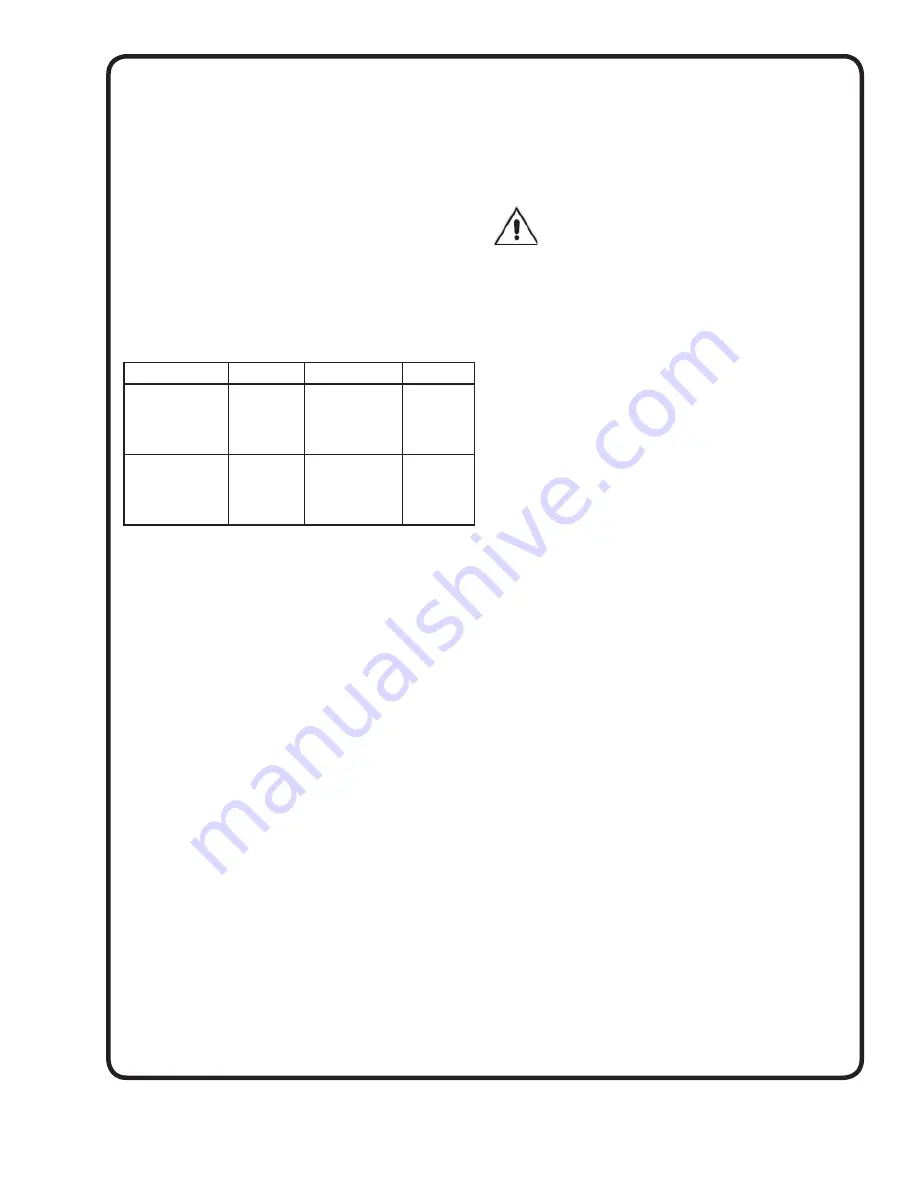
DESCRIPTION LOCTITE® PERMA-LOC® STALOC®
Thread Locking
Compound
#242 (General
Purpose)
242
MM5
T42
Thread Locking
Compound #
RC609 (High
Strength)
RC609
HM128
T70
C-7) Lifting Chain Installation:
For models 6SE_____L and 6SE____HL, optional lifting
chain (5/16” dia. proof coil chain, hot galvanized) is looped
through lifting yoke and fastened together with two 3/8”
steel, zinc plated cold shut. Force cold shut closed and weld
together.
For models 6SE____EHA (Standard units) and models
6XSE____A and 6XSE____EHA, (Non-Sparking units),
optional lifting chain (5/16, or 3/8” dia. proof coil chain, hot
galvanized, sized to match lifting chain assembly supplied
with pump) is fastened to pump chain with a 3/8, or 7/16”
steel, zinc plated cold shut. Cold shut is supplied with pump
motor chain.
NOTE:
Pumps are supplied from manufacturer
with motor chain aligned with discharge fl ange (see Figure
6). Find center of pump motor chain. Find chain link 1
to 1-1/2 links away from center on side opposite pump
discharge. Insert cold shut in this link. Attach to lifting chain.
Force cold shut closed and weld together. When pump is
lifted, pump discharge should tilt below horizontal centerline
from 5 to 10”.
C-8) Installation Descent Speed:
When lowering pump into wet well on the guide rails, do not
exceed a descent speed of 3.2 inches per second or 16 feet
per minute.
SECTION D: MAINTENANCE AND REPAIR
D-1) Maintenance:
After pump is lifted for inspection, it is recommended any
foreign material be fl ushed from moveable fi tting, guide
plugs, and stationary base elbow face before replacement
in wet well.
D-2) Repair:
NOTE:
All item numbers in ( ) refer to Figure 7.
D-2.1) Moveable Assembly:
To install a new o-ring in moveable assembly (1),
completely remove o-ring (1B) and thoroughly clean
groove recess in moveable (1A).
NOTE: CARE SHOULD BE TAKEN SO DOVE-
TAILED GROOVE IS NOT DAMAGED WHEN
REMOVING O-RING.
Set moveable (1A) with dove-tail groove up on an arbor
press. Shim and/or clamp moveable so sealing face is
level. Run a light bead of quick set adhesive (Aron Alpha
or equivalent) around center of groove bottom. Set o-ring
(1B) over groove. Place a fl at plate over o-ring (1B), center
under press. Using press, force o-ring (1B) into groove.
Hold for around 1 minute to allow adhesive to set.
NOTE:
DO NOT USE EXCESSIVE PRESSURE AFTER O-RING
SLIPS INTO GROOVE.
D-2.2) Stationary Base Elbow:
To replace Guide Plug(s) (2B) on Stationary Elbow (2A),
remove socket head screw (2C). Inspect o-ring (2D) for
damage or cuts and replace if required. Reassemble by
placing guide plug (2B) on stationary (2A), insert screw
(2C) into guide plug and tighten.
D-2.3) Guide Rail Cap:
To replace Guide Plug(s) (3B) on Guide Rail Cap (3A),
remove socket head screw (3C), washer (3E) and nut
(3F). Inspect o-ring (3D) for damage or cuts and replace
if required. Reassemble by placing guide plug (3B) on
tab of bracket (3A), insert screw (3C) thru guide plug
and assemble washer (3E) and nut (3F) onto screw and
tighten.
D-2.4) Intermediate Support :
To replace Guide Plug(s) (9B) on Intermediate support
(9A), remove socket head screw (9C), washer (9D) and
nut (9E). Inspect o-ring (9F) for damage or cuts and
replace if required. Reassemble by placing guide plug (9B)
on tab of bracket (9A), insert screw (9C) thru guide plug
and assemble washer (9D) and nut (9E) onto screw and
tighten.
SECTION E: REPLACEMENT PARTS
E-1) Ordering Replacement Parts:
When ordering replacement parts, always furnish the
following information:
1. Product
Model
2. Part
Description
3. Part
Number
4. Quantity
Required
5. Shipping
Instructions
6. Billing
Instructions
Product improvements are made from time to time. The
latest part design will be furnished as it is interchangeable
with the old part.
Summary of Contents for 091550
Page 4: ...4 inches mm Figure 1 Figure 2 ...
Page 8: ...8 Figure 6 ...
Page 9: ...9 Figure 7 ...
Page 13: ...13 Notes ...
Page 14: ...14 Notes ...


