background image

Original Operation Manual 


Sweeper 689.03-40 


12 

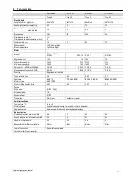
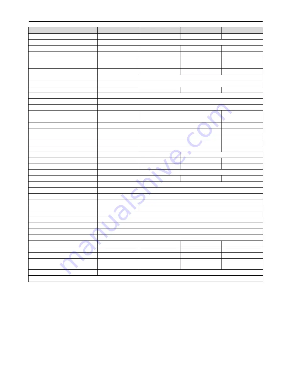
Technical data  


KM Domus 

KM 70 G 

KM 80 G 

KM 100 G 


Type 02 

Type 02 

Type 02 

Type 02 

Machine data 


Length x Width x Height, cm 

86 x74x75 

89x71x76 

89x81x76 

89x101x76 

Deadweight (transport weight), kg 

62 

68 

70 

72 

Drive speed 

Forward km/h 

                              Backward km/h 

2.4 

2.4 

2.4 

2.4 

Brush speed 

280 

280 

280 

280 

Climbing power, max % 

12 

Climbing power with accessories, max % 

Working width, cm 

70 

70 

80 

100 

Support wheel 

360° freely rotatable 

Brush is adjustable 

Left Centre Right 

Motor 


Model 

Briggs & Stratton 
575 ex 

Honda 

GCV 140  /  GCV 160 

Honda 
GCV 160 

Engine size, cm³ 

140 

160  /  160 

160 

Max. motor speed, rpm 

3600 

3100  /  3100 

3100 

Min. motor speed, rpm 

2800 

1600  /  1600 

1600 

Net capacity    KW(HP) at 3600 rpm 

3.3(4.5) 

3,1(4,2)  /  3,3(4,4) 

3.3(4,4) 

Max. permanent capacity  KW(HP) 

2.4(3.3) 

1,9(2,6)  /  2,1(2,8) 

2.1(2.8) 

Fuel type 

Regular petrol, lead-free 


Tank contents, litres 

0.8 

0,93 

0,93 

0,93 

Spark plug  

EMC (Q) 

BPR 6 ES (NGK) 

BPR 6 ES (NGK) 

BPR 6 ES (NGK) 

Motor oil type 

SAE 10W30 

Motor oil filling quantity, litres 

0.44 

0.50 

0.50 

0.50 

Tyres 


Drive wheel 

Ø 300 (4.00-4) 

Air pressure, bar 

1.8 

Support wheel 

Ø 125 

Wheel drive 

Worm gear 

Tandem worm gear 

Ambient conditions 


Temperature, °C 

-5 to +40 

Working ground 

Asphalt, industrial flooring, floor screed, concrete, pavement 

Application area 

Normal use in facilities and landscaping maintenance 

Noise emission 


Guaranteed acoustic power level, dB 

98 

97 

94 

95 

Sound pressure level at operator ear, dB 

85 

84 

81 

82 

Hand-arm vibration, m/s² 

4.2 

<2.5 

2.6 

3.6 

Responsibility limits for components: 

Motor


Motor


Motor


Motor


Year of construction 

See machine nameplate 

Technical modifications reserved! 


Summary of Contents for KM 100 G

Page 1: ...Original Operation Manual 12 2014 Sweeper 689 04 40 Sweeper Operation Manual Models KM 70 G Type 02 KM Domus Type 02 KM 80 G Type 02 KM 100 G Type 02 Machine no ...

Page 2: ...rating elements for all models 6 3 4 Operating elements for KM Domus 7 3 5 Operating elements for KM 70 G KM 80 G KM 100 G 7 3 6 Working position and areas of risk 8 3 7 Accessories and spare parts 8 4 Delivery transport storage 8 4 1 Delivery 8 4 2 Transport 8 4 3 Storage 8 5 Start up first machine inspection 8 5 1 Safety 8 5 2 Requirements at location of use 8 5 3 Assembly 8 5 4 Start up and fun...

Page 3: ...y regulations shall be complied with Other applicable documents Assembly instructions declaration of conformity 1 2 Symbols DANGER This symbol cautions against an immediate threat resulting in serious injuries or death if not avoided WARNING This symbol cautions against a potentially dangerous source of risk which may result in death or serious injury if not avoided ATTENTION Indication of a poten...

Page 4: ...he motor during or after operation Significant risk of burning by hot surfaces Stop the motor and let it cool down before working on the machine as well as before performing maintenance cleaning and repair work Do not refill the tank when the motor is running danger of life by burning and explosion Immediately remove spilled fuel with a cloth danger of life by burning and explosion Keep fuel in de...

Page 5: ...l be disposed of properly and separately in accordance with legal regulations Please do not dispose of any wastes in the environment Packaging materials are recyclable Please make sure that they are collected for reuse Legacy devices contain valuable recyclable materials which should be collected for reuse These devices may be disposed of through appropriate collection systems 3 Design and functio...

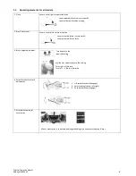
Page 6: ...ever released Brush is at standstill Lever activated Brush turns 3 Brush height adjustment Turn handle to the required setting Use the star screw to secure the setting Turn right Li brush Turn left Brush is lowered 4 Swivel bracket for brush adjustment 1 Lift swivel bracket disengage 2 Select setting centre left right 3 Push back bracket engage 5 Attachment points for accessories Mount accessories...

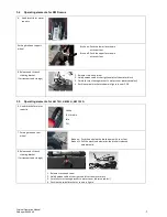
Page 7: ...ket to motor cover observe cables 4 Position swivel bracket as shown in figure in item 3 5 8 3 5 Operating elements for KM 70 G KM 80 G KM 100 G 6 Hand throttle for motor capacity Choke Full throttle Idle Off 7 Parking brake on rear wheel Brake on Push the pedal on the brake down with your foot Brake off Pull the machine backwards the brake is released automatically 8 Release and tilt back steerin...

Page 8: ...rt up 5 Start up first machine inspection 5 1 Safety Unauthorized restart It is prohibited to start the machine while another person is working on it Risks of insufficient order and cleanliness Clean the machine from dried dirt and sand regularly Check the machine for blocking objects Risks of non applied protection devices WARNING Risk of injuries by rotating brushes Parts of the body may be seiz...

Page 9: ...as coal Keep highly flammable materials away from the machine Do not sweep any spilled fuel or similar substances 6 4 Brush setting Height setting of sweeping brush by adjusting the support wheel The bristles of the sweeping brushes should just touch the ground Turn crank to the left Sweeping brush is lowered Turn crank to the right Sweeping brush is lifted An excessively low setting results in an...

Page 10: ...afety precautions X Item 7 3 2 Check all screws for tight fitting O Check motor oil level B Check air filter B Clean or replace air filter normal use B Clean or replace air filter dusty conditions B Adjust tyre pressure O Check sweeping brushes for tapes wrapped around O Check sweeping brush height adjustment X Item 6 4 Check sweeping brush for wear O Check and adjust Bowden cables F Grease rotati...

Page 11: ...and spare parts lists are provided for download on our website www cramer eu 8 3 First action for troubleshooting Failure Error message Remedy Notes Motor does not start Low motor capacity Check throttle position START Refill tank Open fuel tap Honda motor Drain spoiled or old fuel from tank and carburettor add fresh fuel Check and clean spark plug replace if required Check air filter clean as req...

Page 12: ...at 3600 rpm 3 3 4 5 3 1 4 2 3 3 4 4 3 3 4 4 Max permanent capacity KW HP 2 4 3 3 1 9 2 6 2 1 2 8 2 1 2 8 Fuel type Regular petrol lead free Tank contents litres 0 8 0 93 0 93 0 93 Spark plug EMC Q BPR 6 ES NGK BPR 6 ES NGK BPR 6 ES NGK Motor oil type SAE 10W30 Motor oil filling quantity litres 0 44 0 50 0 50 0 50 Tyres Drive wheel Ø 300 4 00 4 Air pressure bar 1 8 Support wheel Ø 125 Wheel drive W...

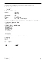
Page 13: ...M 100 G complies with all relevant regulations of the above stated Directive as well as all other applicable Directives including their amendments applicable at the date of this declaration The following other EU Directives were applied EMC Directive 2004 108 EC EU Directive 2000 14 EC The following harmonized standards were applied EN 12733 2001 A1 2009 EN 349 1993 A1 2008 EN 55012 2007 A1 2009 E...

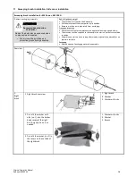
Page 14: ...ne parts separately from packaging Transport inspection Check the machine for completeness and potential damage upon delivery The machine shall be supplied to the specialist dealer in a partially assembled condition Assembly and start up have to be performed by a specialist dealer and or an expert in this field Packaging Please dispose of packaging materials separately Overview 1 Right brush 1 Rig...

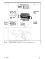
Page 15: ...s fit the washer no 2 in the recess on the outside of the left brush 3 Assemble left and right brush shaft 1 Plug feather key into brush shaft groove 2 Plug brush shaft into gear boring on the left and right by using feather keys 1 Gear boring 2 Feather key 3 Brush shaft Overview 4 Brush assembly 1 Push pre assembled brushes on brush shafts 2 Push threaded rod through entire brush unit 3 Finally p...

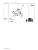
Page 16: ...hreaded rod 3 Side cover left and right rubber Assemble side covers on the left and right As to item 3 1 Position the rubber side covers over the cover plate holes as indicated in the drawing 2 Push screws through holes from below 3 Place punched disc over screw end on the other side and secure it by a locking nut ...

Reviews: