16
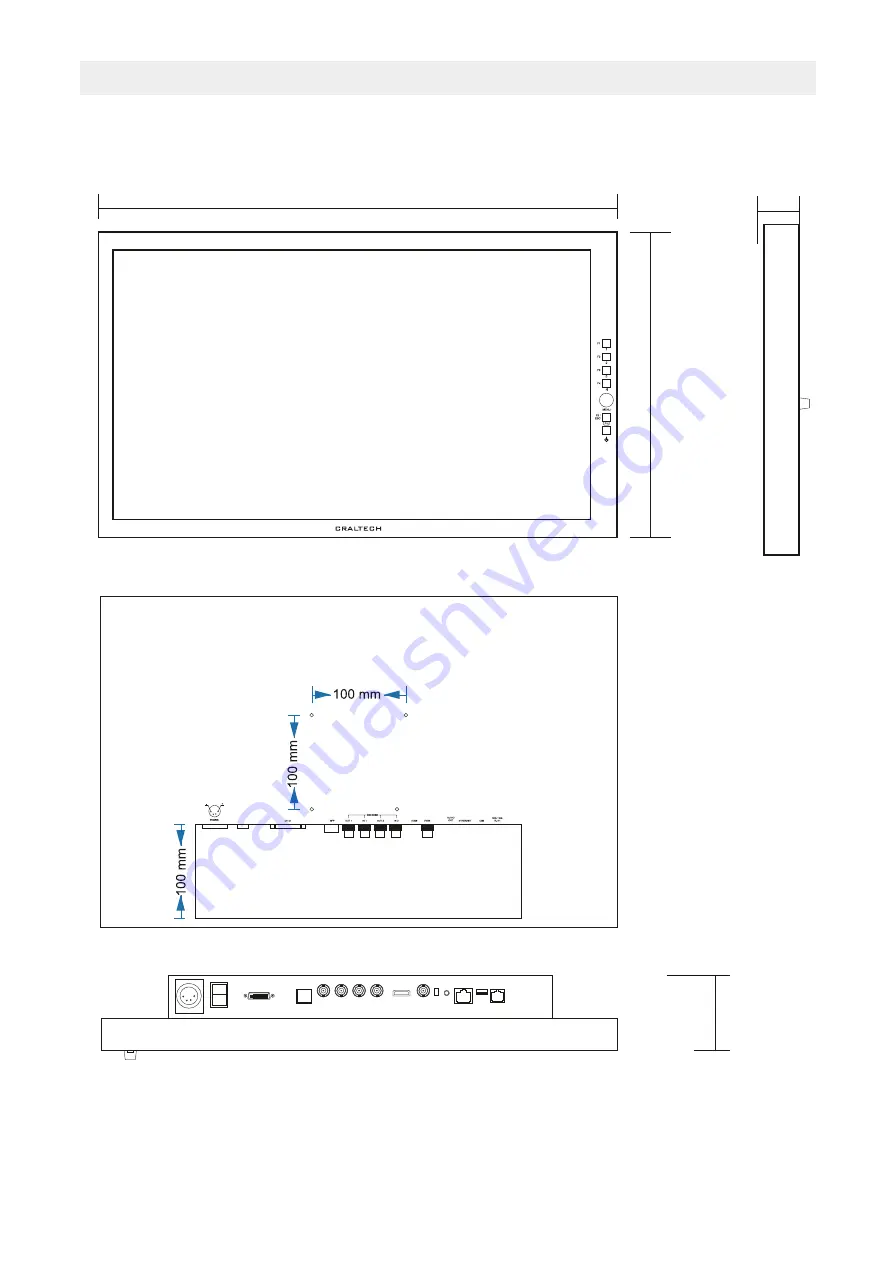
DIMENSIONS
(*) IMPORTANT: Screews must not exceed 8 mm depth into cover.
50 mm
Version 1
Updated 09/09/2020
CM185SL-3G
263 mm
446 mm
Page 1: ...Please read this manual prior to installation and operation and save this manual for future reference CM185SL 3G User Manual Version 1 Updated 09 09 2020 18 5 LCD Monitor ...
Page 2: ...aning the product 5 Do not insert anything into or block the ventilation slots you could get a shock or cause fire 6 Do not remove cover or back to reduce the risk of electric shock 7 Keep the product away from heat sources such as radiators heat registers stoves or other aparatus including amplifiers that produce heat 8 Only use accessories specified by the manufacturer 9 Power Sources This produ...
Page 3: ...2 Controls and Connectors On Screen Menu Image Color Audio Markers Scopes Input Display Alarms Network System Specifications Dimensions 3 4 4 4 5 6 7 8 9 10 11 12 13 14 15 Version 1 Updated 09 09 2020 CM185SL 3G ...
Page 4: ...ed Configurable user key number 5 If menu is selected ESC Move back one position in menu 3 FN Mode Long Press to enable disable CUSTOM configurable F1 to F5 Functions 4 F1 to F5 Direct access to inputs 1 SDI1 2 SDI2 3 HDMI 4 CBVS and Configurable user keys in FN Mode 1 3 2 4 DOUBLE FUNCTIONALITY DIRECT KEYS How to locate a Function in a F1 to F5 direct key To locate a function in F1 to F5 direct k...
Page 5: ...posite Video Input 11 75 Ohm impedance only switch nr 2 12 Audio Out 13 Ethernet connector for remote control 14 USB connector for updates 15 RJ11 RS 422 RS 485 and Tally 12V DC IN SOCKET 1 GND 2 NC 3 NC 4 12V 1 2 3 4 RJ 11 REMOTE CONTROL TSL and GPIO CONNECTOR Used for RS 232 Only one equipment can be controlled PIN 1 RS 232 Out PIN 2 RS 232 In PIN 3 RS 485 PIN 4 RS 485 PIN 5 GND PIN 6 GND 14 4 1...
Page 6: ...der again to Exit adjustment adjustment will be marked in grey and continue navigating 4 Press ESC button to move back to main menu BRIGHTNESS CONTRAST SATURATION Select the adjustment to be modified and use the Encoder up and down to modify value The scale of these adjustments is from 0 to 31 being 15 the value where no Brightness or Contrast or Saturation is applied to the image RGB CHANNEL Sele...
Page 7: ...stment and use the Encoder up and down to modify value 2 Press Menu Encoder again to Exit adjustment YELLOW RED LEVEL Used to select Yellow Red Level 1 Select Yellow Red Level adjustment and use the Encoder up and down to modify value 2 Press Menu Encoder again to Exit adjustment METERS SIZE Used to select Audio Level Meters size Values are Small Large 1 Select Meters Size adjustment and use the E...
Page 8: ...s Menu Encoder again to Exit adjustment SDI1 OFF OFF OFF 000 000 White OFF MARKER H V Select USER option at Markers Adjustment 1 Select Marker H V adjustment and press the encoder to enter 2 Use the Encoder up and down to modify value 3 Press Menu Encoder again to Exit adjustment 1 Select the MARKERS menu and press the encoder to enter 2 Press Menu Encoder to select the adjustment to be modified a...
Page 9: ... and press the encoder to enter 2 Use the Encoder up and down to modify value 3 Press Menu Encoder again to Exit adjustment VECTORSCOPE Used to enable disable Vectorsope 1 Select Vectorsope adjustment and press the encoder to enter 2 Use the Encoder up and down to enable disable 3 Press Menu Encoder again to Exit adjustment NOTE Vectorscope graticules are adapted automatically to HD and SD if Data...
Page 10: ...der again to Exit adjustment ASPECT RATIO Used to select Aspect Ratio Values are 4 3 and 16 9 Data Conversion is used to select the mode of data conversion form YCbCr to RGB Values are REC 601 REC 709 and AUTO Default Value is AUTO AUTO mode uses REC 601 data conversion for SD SDI inputs and REC 709 data conversion for HD SDI inputs DATA CONVERSION 1 Select the INPUT menu and press the encoder to ...
Page 11: ...ech SFP1 TO SDI1 This function activates input 1 of SFP Module This input will be multiplexed with SDI 1 of the monitor SFP2 TO SDI2 This function activates input 2 of SFP Module This input will be multiplexed with SDI 2 of the monitor IMAGE COLOR AUDIO MARKERS SCOPES INPUT DISPLAY ALARMS NETWORK SYSTEM PIXEL TO PIXEL 1 1 Used to Enable Disable 1 1 Function FOCUS ASSIST Used to Enable Disable Focu...
Page 12: ...o activate Video Black Alarm using Alarm per input SFX 3G By Craltech IMAGE COLOR AUDIO MARKERS SCOPES INPUT DISPLAY ALARMS NETWORK SYSTEM VIDEO LOSS Used to Enable Disable Video Loss Alarm per input This alarm will be only active in the input selected in Alarm per input AUDIO LOSS Used to Enable Disable Audio Loss Alarm per input This alarm will be only active in the input selected in Alarm per i...
Page 13: ...l the inputs Select OFF to disable Video Loss Alarm in all the inputs Select Per Input to activate Video Loss Alarm using Alarm per input VIDEO LOSS COLOR Used to select Video Loss alarm color AUDIO LOSS MODE Audio Loss Mode alarm can be activated per input or for ALL inputs Video Loss Mode values are Per Input ALL and OFF Select ALL to activate Audio Loss Alarm in all the inputs Select OFF to dis...
Page 14: ...ot stand by the equipment then switch ON the equipment to start with new configuration UDP PORT This option is used to modify UDP PORT 1 Select UDP PORT adjustment and press the encoder to enter 2 Use the Encoder up and down to modify values 3 To apply the new Network configuration Select Yes at Apply Config in Network Menu and unplug not stand by the equipment Apply Config This option is used to ...
Page 15: ...SL ON ON Small 00 00 No Rec709 NO NO Backlight Equipment ID Encoder Sensitivity Fn Keys Mode Keys Light Tally UMD Source Display on UMD Display Squares OSD Size OSD x y Position OSD Transparency Start Calibration Display Data Conv Factory Default Update Firmware 1 Select the SYSTEM menu and press the encoder to enter 2 Press Menu Encoder to select the adjustment to be modified adjustment will be m...
Page 16: ...1080p 60 59 84 50 30 29 97 25 24 23 98 25sF 24sF 23 98sF 1080i 60 59 94 50 720p 60 59 94 50 480i 59 94 576i 50 16 9 4 3 Embedded Audio 16 Channel Audio Level Meter SDI inputs Analog Stereo Phone Jack 2 x Speakers 1 5W Stereo 16 characters IMD TSL comp Green and Red TSL comp Color waveform YCbCr Y Cb Cr RGB R G B Color Vectorscope Ethernet Aluminium Textured Black Powder Coat 446 x 263 x 50 mm 2 9K...
Page 17: ...16 DIMENSIONS IMPORTANT Screews must not exceed 8 mm depth into cover 50 mm 50 mm Version 1 Updated 09 09 2020 CM185SL 3G 263 mm 446 mm ...