background image

13

OPERATION

Auger Control

The auger control is located on the left handle. Squeeze the control 
grip against the handle to engage the augers and start snow throwing 
action. Release to stop.

Drive Control/ Auger Control Lock

The drive control is located on the right handle. Squeeze the control 
grip against the handle to engage the wheel drive. Release to stop. 
The drive control also locks the auger control so you can operate 
the chute directional control without interrupting the snow throwing 
process. If the auger control is engaged simultaneously with the drive 
control, the operator can release the auger control (on the left handle) 
and the augers will remain engaged. Release both controls to stop the 
augers and wheel drive. 
IMPORTANT: Always release the drive control before changing 
speeds.

Augers

When engaged, the augers rotate and draw snow into the auger 
housing.

Skid Shoes

Position the skid shoes based on surface conditions. Adjust upward 
for hard-packed snow. Adjust downward when operating on gravel or 
crushed rock surfaces. See “Making Adjustment” Section.

Wheel Steering Controls

The left and right wheel steering controls are located on the underside 
of the handles. Squeeze the right control to turn right; squeeze the left 
control to turn left. 

NOTE: Operate the snow thrower in open areas until you are familiar 
with these controls.

Four-Way Chute Control™

The chute directional control is located on the left side of the dash 
panel.
•  To change the direction in which snow is thrown, squeeze the 

button on the joy-stick and pivot the joy-stick to the right or to the 
left.

•  To change the angle/distance which snow is thrown, pivot the 

joy-stick forward or backward.

Chute Clean-Out Tool

The clean-out tool is conveniently fastened to the rear of the auger 
housing with a mounting clip. 
1.  Release both the auger control and the drive/auger control lock.
2.  Stop the engine by pushing the rocker switch to the “OFF” position, 

pull out the safety key.

3.  Remove the clean-out tool from the mounting clip. 
4.  Use the shovel-shaped end of the clean-out tool to remove any 

snow and ice in the chute assembly.

5.  Re-fasten the clean-out tool to the mounting clip on the rear of the 

auger housing and restart engine.

6.  While standing in the operator’s position (behind the snow thrower), 

engage the auger control for a few seconds to clear any remaining 
snow or ice from the chute assembly before continuing to clear 
snow.

WARNING: Never use your hands to clean snow and 
ice from the chute assembly or auger housing.

Headlight

The headlight is on whenever the engine is running.

Heated Handles Switch (If Equipped)

This switch is located on the rear of the snow thrower dash panel. To 
activate the heated handles, toggle the switch to the “ON” position to 
generate heat within the handle grips. Toggle the switch to the “OFF” 
position after using the snow thrower.

NOTE: The heated handles grips are a compliment to, not a substitute 
for, proper cold weather outerwear for the operator’s hands. It is 
recommended that the snow thrower operator wear gloves/mittens to 
avoid extremities

AUGER

CONTROL

GO

DRIVE

CONTROL

GO

Summary of Contents for C459-52925

Page 1: ...les and operating instructions Operator s Manual SAFETY ASSEMBLY OPERATION MAINTENANCE PARTS LIST Sears Canada Inc 290 Yonge Street Toronto On M5B 2C3 Visit our web sears ca 7 20 2009 FORM NO 769 05208 28 30 Steerable Snowthrowers Model No C459 52927 28 Model No C459 52925 30 ...

Page 2: ...2 199260 07 21 05 BY Printed in U S A 02488 ...

Page 3: ...ng normal use such as belts spark plugs air cleaners and shear pins as well damage to the 2 engine resulting from operating snow thrower with insufficient oil Repairs necessary because of operator abuse or negligence including the failure to operate and maintain 3 the equipment according to the instructions contained in the Owner s Manual 4 Tire replacement or repair caused by punctures from outsi...

Page 4: ...ettes cigars pipes and other sources of ignition c Never fuel machine indoors d Never remove gas cap or add fuel while the engine is hot or running e Allow engine to cool at least two minutes before refueling f Never over fill fuel tank Fill tank to no more than inch below bottom of filler neck to provide space for fuel expansion g Replace gasoline cap and tighten securely h If gasoline is spilled...

Page 5: ...ol levers and stop the engine Wait until the auger impeller come to a complete stop Disconnect the spark plug wire and ground against the engine to prevent unintended starting 3 Check bolts and screws for proper tightness at frequent intervals to keep the machine in safe working condition Also visually inspect machine for any damage 4 Do not change the engine governor setting or over speed the eng...

Page 6: ... amputate hands and feet WARNING THROWN OBJECTS This machine may pick up and throw and objects which can cause serious personal injury WARNING GASOLINE IS FLAMMABLE Allow the engine to cool at least two minutes before refueling WARNING CARBON MONOXIDE Never run an engine indoors or in a poorly ventilated area Engine exhaust contains carbon monoxide an odorless and deadly gas WARNING ELECTRICAL SHO...

Page 7: ...NOTES 7 ...

Page 8: ...n hand knobs securing upper handle to lower handle Chute Assembly 1 Remove cotter pin wing nut and hex screw from chute control assembly and clevis pin and cotter pin from chute support bracket See Figure 2 2 Insert round end of the hex rod hole pointing upward as far as possible into chute control assembly See Figure 3 3 Place chute onto chute base with the hex rod positioned under the handle pan...

Page 9: ... hex end of the rod hole pointing upward into the pinion gear See Figure 8 7 Secure the round end of the hex rod to the chute control assembly with the cotter pin removed earlier See Figure 9 NOTE The second hole is used to achieve further engagement of the hex rod into the pinion gear if required refer to Chute Control Rod in the Adjustment section 8 Finish securing chute rotation assembly to chu...

Page 10: ...instructions carefully and perform all adjustments to verify your snow thrower is operating safely and properly Clean Out Tool The clean out tool is mounted to the rear of the auger housing with a mounting clip and a cable tie at the factory Cut the cable tie before operating the snow thrower See Figure 11 WARNING Never use your hands to clean snow and ice from the chute assembly or auger housing ...

Page 11: ...lugged into the hole in the lower handle Pull the slack portion of the wiring harness through the cable tie to prevent interference with the recoil starter handle See Figure 13 Skid Shoes Position the skid shoes based on surface conditions Adjust upward for hard packed snow Adjust downward when operating on gravel or crushed rock surfaces See Making Adjustment Section Tire Pressure The tires are o...

Page 12: ...revent unauthorized use of equipment Rocker Switch The rocker switch is used to stop the engine The switch must be in the ON position in order to start the engine Figure 14 Now that you have set up your snow thrower for operation get acquainted with its controls and features These are described below and illustrated in Figure 14 This knowledge will allow you to use your new equipment to its fulles...

Page 13: ...o change the direction in which snow is thrown squeeze the button on the joy stick and pivot the joy stick to the right or to the left To change the angle distance which snow is thrown pivot the joy stick forward or backward Chute Clean Out Tool The clean out tool is conveniently fastened to the rear of the auger housing with a mounting clip 1 Release both the auger control and the drive auger con...

Page 14: ... again 5 When disconnecting the extension cord always unplug the end at the three prong wall outlet before unplugging the opposite end from the snow thrower Recoil Starter 1 Grasp the recoil starter handle and slowly pull the rope out At the point where it becomes slightly harder to pull the rope slowly allow the rope to recoil 2 Pull the starter handle with a firm rapid stroke Do not release the ...

Page 15: ...he operator s position behind the snow thrower engage the auger 4 Allow the auger to remain engaged for approximately ten 10 seconds before releasing the auger control Repeat this several times 5 With the auger control in the disengaged up position walk to the front of the machine 6 Confirm that the auger has completely stopped rotating and shows NO signs of motion If the auger shows ANY signs of ...

Page 16: ...einsert the cotter pin through this hole and the chute control rod See Figure 11 Drive Control Shift Lever When the drive control is released and in the disengaged up position the cable should have very little slack It should NOT be tight Check the adjustment of the drive control as follows 1 With the drive control released push the snow thrower gently forward The unit should roll freely 2 Engage ...

Page 17: ...at you operate this snow thrower on gravel as loose gravel can be easily picked up and thrown by the auger causing personal injury or damage to the snow thrower If for some reason you have to operate the snow thrower on gravel keep the skid shoe in the highest position for maximum clearance between the ground and the shave plate The space between the skid shoes and the ground can be adjusted For c...

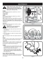
Page 18: ...er housing 2 Remove the lower frame cover by removing the screws which secure it 3 Apply a light coating of an all weather multi purpose oil to the hex shaft See Figure 20 NOTE Avoid getting oil on rubber friction wheel and aluminum drive plate Wheels At least once a season remove both wheels Clean and coat the axles with a multipurpose automotive grease before reinstalling wheels Auger Shaft At l...

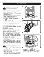
Page 19: ...by remov ing the two self tapping screws See Figure 23 2 Carefully pivot the snow thrower up and forward so that it rests on the auger housing Remove the frame cover from the underside of the snow thrower by removing four self tapping screws which secure it See Figure 24 3 Roll the auger belt off the engine pulley See Figure 25 4 a Loosen and remove the shoulder screw which acts as a belt keeper S...

Page 20: ... required and several components must be removed and in order to replace the snow thrower s friction wheel rubber See an authorized Service Dealer to have the friction wheel rubber replaced or phone Customer Support as instructed on page 2 for information on ordering a Service Manual To inspect the friction wheel proceed as follows 1 Carefully pivot the snow thrower up and forward so that it rests...

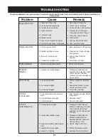
Page 21: ...ap Be certain vent is clear 3 Contact Service Center 1 Spark plug wire loose 2 Gas cap vent plugged 3 Exhaust port plugged Unit fails to propel itself 1 Adjust drive control cable Refer to Adjustments 2 Replace drive belt 3 Replace friciton wheel 1 Drive control cable in need of adjust ment 2 Drive belt loose or damaged 3 Friction wheel worn Excessive Vibration 1 Loose parts or damaged auger 1 Sto...

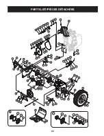
Page 22: ... 22 64 66 52 21 17 37 29 2 34 33 47 49 40 32 56 A A 25 12 15 11 27 53 23 24 23 46 57 41 45 48 42 31 10 61 9 28 20 30 7 8 4 18 3 1 6 14 26 19 16 13 50 51 46 62 50 39 43 38 44 5 35 63 36 58 59 60 22 22 22 22 65 67 60 43 59 58 54 11 ...

Page 23: ...4 x 0 75 po de lg 32 710 04370 Hex Hd Cap Scr 1 4 20 x 3 0 Gr 5 Vis à tête hex 1 4 20 x 3 0 Qual 5 33 731 04426A Upper Chute Goulotte supérieur 34 618 04801 Gearbox Assembly 4 way Boîtier d engrenage 4 fonctions 35 710 04187 Hi Lo Screw 1 4 15 x 50 Vis 1 4 15 x 0 50 36 753 06151 4 Way Chute Control Assembly Kit Trousse de la commande de la goulotte à 4 fonctions 37 749 04191A Upper Handle LH Guido...

Page 24: ...t être légèrement différent 61 30 in po 7 39 64 62 63 26 38 7 4 9 7 66 67 AUGER HOUSING COMPONENTS COMPOSANTS DU LOGEMENT DES TARIÈRES SIZE TAILLE AUGER HOUSING LOGEMENT DES TARIÈRES AUGER AXLE ESSIEU DES TARIÈRES SHAVE PLATE LAME PLATE GEARBOX ASS Y ENSEMBLE DE LA VIS SANS FIN SPACERS ENTRETOISE WORM GEAR ENGRENAGE 24 684 04265 711 04285 790 00120 618 04171A 731 04870 1 717 04449 28 684 04268 711...

Page 25: ...llet à bride 34 790 00087A Bushing Housing Carter de la collet 790 00138A Bushing Housing w grease fitting hole Carter de la collet avec trou pour raccord de graissage 35 See chart on page 24 Voir tableau à la page 24 38 790 00181 Drift Cutter Optional Virole de réglage en option 39 790 00091 Reversible Slide Shoe steel Patin réversible acier 40 737 3000 Grease Fitting optional Raccord de graissag...

Page 26: ...17 16 14 70 4 68 1 18B 12 25 23 12 70 23 9 24 44 22 25 8 40 5 41 1 A A 45 6 69 38 27 26 46 43 26 27 42 61 36 62 60 51 55 52 53 58 50 49 48 47 67 59 20 54 19 64 64 72 65 66 63 56 57 56 28 18A 14 16 43 42 42A 42E 42B 42C 42F 42D 42H 42G 43A 77 43B 43 71 74 76 73 39 13 82 75 81 80 30 1 83 35 21 79 2 ...

Page 27: ... 711 04416A Hex Drive Shaft 500 Arbre d entraînement 500 42B 618 04284 Planetary Carrier Ass y Porte roue 42C 717 1209A Gear 12T Engrenage 12 dents 42D 736 0502 Flat Washer 58 x 1 12 x 02 Rondelle plate 0 58 x 1 12 x 0 02 42E 736 0336 Flat Washer 5 8 ID x 1 0 OD Rondelle plate 5 8 DI x 1 0 DE 42F 717 1210A Gear 18T Engrenage 18 dents 42G 618 04285 Ring Planetary Gear Ass y 500 Ensemble de l engren...

Page 28: ...28 NOTES For parts and or accessories refer to customer support on page 2 Adressez vous au Service après vente à la page 2 pour ce qui concerne les pièces et ou accessoires ...

Page 29: ...29 NOTES For parts and or accessories refer to customer support on page 2 Adressez vous au Service après vente à la page 2 pour ce qui concerne les pièces et ou accessoires ...

Page 30: ...23 NOTES For parts and or accessories refer to customer support on page 2 Adressez vous au Service après vente à la page 2 pour ce qui concerne les pièces et ou accessoires ...

Page 31: ...e 1 Carbureteur est mal réglé Moteur surchauffe Perte de puissance 1 Branchez et serrez le fil de la bougie 2 Dégagez la glace et la neige du chapeau Assurez vous de la propreté d aération 3 Adressez vous à une station technique 1 Fil de la bougie desserré 2 Chapeau d échappement d aération bouché 3 Le port déchappement est bouché La souffleuse n avance pas 1 Réglez le câble d entraînement Voir le...

Page 32: ...re 24 2 Démontez le couvre châssis du dessous de la souffleuse en retirant les quatre vis auto taraudeuses qui le maintiennent en place Voir la Figure 24 3 Examinez soigneusement la roue de frottement pour détecter tout signe d usure ou de fendillement Voir la Figure 29 Instructions de remisage Si le moteur doit être entreposé pendant plus de 30 jours préparez le de la façon selon les instructions...

Page 33: ...le couvre courroie en plastique sur le devant du moteur en enlevant les deux vis auto taraudeuses Voir la Figure 23 2 Basculez doucement la souffleuse vers l avant pour la faire reposer sur l habitacle de la tarière Voir la Figure 24 3 Démontez le couvre châssis du dessous de la souffleuse en retirant les quatre vis auto taraudeuses qui le maintiennent en place 4 a Dégagez la courroie de la tarièr...

Page 34: ...ulons ordinaires et le contre écrous à embase qui la maintiennent ainsi que les patins sur la souffleuse 2 Installez la lame plate neuve en vérifiant que la tête des boulons ordinaires se trouve à l intérieur de l habitacle Serrez à fond Remplacement de la courroie de la tarière AVERTISSEMENT Laissez tourner le moteur jusqu à ce qu il tombe en panne d essence avant de faire basculer la souffleuse ...

Page 35: ... basculer la souffleuse 1 Basculez doucement la souffleuse vers l avant pour la faire reposer sur l habitacle de la tarière 2 Enlevez le couvre châssis en enlevant les deux vis auto taraudeus es qui le maintient 3 Appliquez une légère couche d huile polyvalente toutes saison sur l arbre hex Voir la Figure 20 REMARQUE Évitez de renverser de l huile sur la roue de frottement en caoutchouc ou sur la ...

Page 36: ...nférieur sur le support indexé du câble de transmission et relevez ou abais sez le support selon le besoin Voir la Figure 15 Serrez l écrou à sic pans inférieur pour maintenir le support à la position correcte 5 Replacez le couvre châssis et redressez la souffleuse à la position de fonctionnement Patins L espace entre la lame plate et le sol peut être ajusté en ajustant les patins Pour déblayer co...

Page 37: ...e commande de la goulotte jusqu à ce que le trou dans celle ci s aligne avec le deuxième trou dans l ensemble de commande de la goulotte Voir la Figure 17 3 Réinsérez la goupille fendue par ce trou et la tige de commande de la goulotte Voir la Figure 17 Commande de la transmission et levier de vitesses Le câble doit présenter très peu de jeu quand la commande de la transmission est débrayée et en ...

Page 38: ...utefois être tendu 2 Choisissez un endroit bien aéré et faites démarrer la souffleuse selon les instructions dans le paragraphe pour faire démarrer le moteur Vérifiez que l obturateur est réglé à la position rapide 3 Tenez vous à la position de conduite derrière la souffleuse et enclenchez la tarière 4 Attendez environ dix secondes avant de débrayer la tarière Répétez cette opération plusieurs foi...

Page 39: ...ur se mette en route 3 Quand le moteur démarre lâchez le bouton du démarreur immédiate ment 4 Au fur et à mesure que le moteur chauffe tournez lentement le bouton du volet de départ vers la position SANS VOLET Si le moteur hésite tournez à nouveau le bouton du volet de départ à la position VOLET PLEIN puis revenez lentement à la position SANS VOLET 5 Débranchez d abord le fil électrique de la pris...

Page 40: ...r l orientation de la projection de la neige appuyez sur le bouton du levier de commande et tournez le levier vers la droite ou vers la gauche Pour modifier l angle la distance de projection de la neige poussez le levier de commande vers l avant ou tirez le vers l arrière Outil de dégagement de la goulotte Cet outil est maintenu sur l arrière de l habitacle de la tarière par une attache 1 Débrayez...

Page 41: ...pour que le moteur démarre Enlevez la clé de sécurité pour éviter toute utilisation non autorisée de l équipement Interrupteur à bascule Il sert à arrêter le moteur et doit se trouver à la position On pour la mise en marche du moteur Figure 14 Maintenant que votre souffleuse est prête à travailler il est temps de vous familiariser avec ses commandes et diverses caractéristiques expliquées ci desso...

Page 42: ...ur doit être enfoncée dans le trou du guidon inférieur Faites passer la partie détendue du faisceau de câbles dans l attache pour éviter toute interférence avec la poignée du démarreur à lanceur Voir la Figure 13 Patins Positionnez les patins en fonction de la surface de travail Redressez les si la neige est tassée et abaissez les pour travailler sur des surfaces recouvertes de gravier ou de pierr...

Page 43: ...che câble et jetez le avant d utiliser la souffleuse AVERTISSEMENT Avant d utiliser votre souffleuse référez vous à Test de la commande de la tarière dans le chapitre Fonctionnement Lisez et suivez soigneusement les instructions et effectuez tous les ajustements pour vérifier que votre souffleuse Outil de dégagement de la goulotte L outil de dégagement de la goulotte est fixée avec un support de m...

Page 44: ...ssous du tableau de bord REMARQUE Le levier de commande devrait être légèrement incliné vers la droite comme illustré à la Figure 6 et la flèche sur le pignon sur le haut pour assurer le pivotement complet de la goulotte 6 Tout en soutenant l arrière du pignon insérez l extrémité hex de la tige trou vers le haut dans le pignon Voir la Figure 8 7 Fixez l extrémité ronde de la tige hex au commande d...

Page 45: ...re 1 Alignez le guidon supérieur avec le guidon inférieur b Serrez les boutons qui maintiennent le guidon supérieur sur le guidon inférieur Goulotte 1 Retirez la goupille fendue l écrou à oreilles et la vis hex qui se trouvent sur la commande de la goulotte ainsi que la goupille fendue et l axe de chape sur le support de la goulotte Voir la Figure 2 2 Insérez l extrémité ronde de la tige hex trou ...

Page 46: ...NOTES 7 ...

Page 47: ...S PROJETÉS Cette machine peut ramasser et projeter des objets ce qui peut causer des blessures graves AVERTISSEMENT L ESSENCE EST UN PRODUIT INFLAMMABLE Laissez le moteur refroidir pendant au moins deux minutes avant de refaire le plein AVERTISSEMENT MONOXYDE DE CARBONE Ne faites jamais fonctionner un moteur à l intérieur ou dans un bâtiment mal ventilé Les gaz d échappement contiennent du monoxyd...

Page 48: ...êtez le moteur Attendez que la tarière turbine se soit complètement immobilisée Débranchez le fil de la bougie et mettez le à la terre pour empêcher tout démarrage accidentel pendant le nettoyage la réparation ou l examen de la machine 3 Vérifiez régulièrement que les boulons et vis sont bien serrés et maintenez la machine en bon état de marche Examinez soigneusement la machine pour vous assurer q...

Page 49: ...ais le capuchon d essence et n ajoutez pas d essence pendant que le moteur tourne e Laissez le moteur refroidir pendant au moins deux minutes avant de faire le plein f Ne faites jamais déborder le réservoir Laissez un espace d un demi pouce environ pour permettre l expansion du carburant g Resserrez bien le capuchon d essence h En cas de débordement essuyez toute éclaboussure sur le moteur et la m...

Page 50: ...male comme les courroies les bougies les filtres à air et les goupilles de cisaillement ainsi que tout dégât 2 au moteur résultant de l utilisation de la souffleuse avec une quantité d huile insuffisante Les réparations nécessaires en raison de l utilisation abusive ou négligente y compris l utilisation et l entretien de l équipement ne re 3 spectant pas les instructions fournies dans la notice d ...

Page 51: ...s proche afin d apporter à l atelier des produits tels que des aspirateurs tondeuses à gazon ou appareils électroniques Pour connaître le no de téléphone du Service des pièces et de l entretien Sears afin de commander les pièces de rechange accessoires et manuels d instructions requis pour effectuer vous même les réparations www sears ca Pour acheter ou demander des renseignements sur un contrat d...

Page 52: ...a machine Notice d utilisation SÉCURITÉ MONTAGE UTILISATION ENTRETIEN PIÈCES DÉTACHÉES Sears Canada Inc 290 Yonge Street Toronto On M5B 2C3 Visitez notre site web sears ca Souffleuse à neige orientable des 28 po et 30 po Modèle No C459 52927 28 po Modèle No C459 52925 30 po 7 20 2009 FORM NO 769 05208 ...

Reviews: