background image

3

SAFETY INSTRUCTIONS

TRAINING

1.  Read, understand, and follow all instructions on the machine and in the 

manual(s) before attempting to assemble and operate. Keep this manual in 

a safe place for future and regular reference and for ordering replacement 

parts. 

2.  Be familiar with all controls and their proper operation. Know how to stop 

the machine and disengage them quickly.

3.  Never allow children under 14 years old to operate this machine. Children 

14 years old and over should read and understand the instructions and safe 

operation practices in this manual and on the machine and be trained and 

supervised by an adult.

4.  Never allow adults to operate this machine without proper instruction. 
5.  Thrown objects can cause serious personal injury. Plan your snow-throwing 

pattern to avoid discharge of material toward roads, bystanders and the like. 

6.  Keep bystanders, helpers, pets and children at least 75 feet from the 

machine while it is in operation. Stop machine if anyone enters the area.

7.  Exercise caution to avoid slipping or falling, especially when operating in 

reverse.

PREPARATION

Thoroughly inspect the area where the equipment is to be used. Remove all 
doormats, newspapers, sleds, boards, wires and other foreign objects, which 
could be tripped over or thrown by the auger/impeller. 
1.  Always wear safety glasses or eye shields during operation and while 

performing an adjustment or repair to protect your eyes. Thrown objects 
which ricochet can cause serious injury to the eyes.

2.  Do not operate without wearing adequate winter outer garments. Do not 

wear jewelry, long scarves or other loose clothing, which could become 
entangled in moving parts. Wear footwear which will improve footing on 
slippery surfaces. 

3.  Use a grounded three-wire extension cord and receptacle for all units with 

electric start engines. 

4.  Adjust collector housing height to clear gravel or crushed rock surfaces. 
5.  Disengage all control levers before starting the engine. 
6.  Never attempt to make any adjustments while engine is running, except 

where specifically recommended in the operator’s manual.

7.  Let engine and machine adjust to outdoor temperature before starting to 

clear snow. 

Safe Handling of Gasoline

To avoid personal injury or property damage use extreme care in handling 
gasoline. Gasoline is extremely flammable and the vapors are explosive. 
Serious personal injury can occur when gasoline is spilled on yourself or your 
clothes, which can ignite. Wash your skin and change clothes immediately.
  a.  Use only an approved gasoline container.
  b.  Extinguish all cigarettes, cigars, pipes and other sources of ignition.
  c.  Never fuel machine indoors. 
  d.  Never remove gas cap or add fuel while the engine is hot or running. 
  e.  Allow engine to cool at least two minutes before refueling.
  f.  Never over fill fuel tank. Fill tank to no more than ½ inch below bottom 

of filler neck to provide space for fuel expansion.

  g.  Replace gasoline cap and tighten securely.
  h.  If gasoline is spilled, wipe it off the engine and equipment. Move 

machine to another area. Wait 5 minutes before starting the engine.

  i.  Never store the machine or fuel container inside where there is an open 

flame, spark or pilot light (e.g. furnace, water heater, space heater, 
clothes dryer etc.). 

  j.  Allow machine to cool at least 5 minutes before storing
  k.  Never fill containers inside a vehicle or on a truck or trailer bed with a 

plastic liner. Always place containers on the ground away from your 
vehicle before filling.

  l.  If possible, remove gas-powered equipment from the truck or trailer and 

refuel it on the ground. If this is not possible, then refuel such equip-
ment on a trailer with a portable container, rather than from a gasoline 
dispenser nozzle.

  m. Keep the nozzle in contact with the rim of the fuel tank or container 

opening at all times until fueling is complete. Do not use a nozzle 
lock-open device.

OPERATION

1.  Do not put hands or feet near rotating parts, in the auger/impeller housing 

or chute assembly. Contact with the rotating parts can amputate hands 
and feet. 

2.  The auger/impeller control lever is a safety device. Never bypass its 

operation. Doing so makes the machine unsafe and may cause personal 
injury. 

3.  The control levers must operate easily in both directions and automatically 

return to the disengaged position when released. 

4.  Never operate with a missing or damaged chute assembly. Keep all safety 

devices in place and working.

Your Responsibility: 

Restrict the use of this power machine to 

persons who read, understand, and follow the warnings and instruc-
tions in this manual and on the machine.

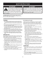
DANGER

This machine was built to be operated according to the rules for 
safe operation in this manual. As with any type of power equipment, 
carelessness or error on the part of the operator can result in serious 
injury. This machine is capable of amputating hands and feet and 
throwing objects. Failure to observe the following safety instructions 
could result in serious injury or death.

WARNING

This symbol points out important safety instructions 
which, if not followed, could endanger the personal 
safety and/or property of yourself and others. Read 
and follow all instructions in this manual before 

attempting to operate this machine. Failure to comply with these 
instructions may result in personal injury. When you see this symbol, 
HEED ITS WARNING!

Summary of Contents for C459-52233

Page 1: ... 52233 SAFETY ASSEMBLY OPERATION MAINTENANCE PARTS LIST CAUTION Before using this product read this manual and follow all safety rules and operating instructions Sears Canada Inc 290 Yonge Street Toronto On M5B 2C3 Visit our web site sears ca 9 10 2012 769 08250 ...

Page 2: ...ion 12 Service Maintenance 17 Off Season Storage 25 Troubleshooting 26 Parts List 28 Warranty Statement 39 1 800 4 MY HOME 40 TABLE OF CONTENTS Model Number Serial Number Date of Purchase Record the model number serial number and date of purchase above MODEL NUMBER ...

Page 3: ...ettes cigars pipes and other sources of ignition c Never fuel machine indoors d Never remove gas cap or add fuel while the engine is hot or running e Allow engine to cool at least two minutes before refueling f Never over fill fuel tank Fill tank to no more than inch below bottom of filler neck to provide space for fuel expansion g Replace gasoline cap and tighten securely h If gasoline is spilled...

Page 4: ...ol levers and stop the engine Wait until the auger impeller come to a complete stop Disconnect the spark plug wire and ground against the engine to prevent unintended starting 3 Check bolts and screws for proper tightness at frequent intervals to keep the machine in safe working condition Also visually inspect machine for any damage 4 Do not change the engine governor setting or over speed the eng...

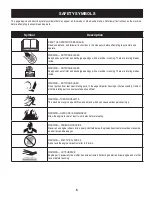
Page 5: ... amputate hands and feet WARNING THROWN OBJECTS This machine may pick up and throw and objects which can cause serious personal injury WARNING GASOLINE IS FLAMMABLE Allow the engine to cool at least two minutes before refueling WARNING CARBON MONOXIDE Never run an engine indoors or in a poorly ventilated area Engine exhaust contains carbon monoxide an odorless and deadly gas WARNING ELECTRICAL SHO...

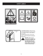
Page 6: ...assembly of ice and snow This item is fastened with a cable tie at the factory Cut the cable tie before operating the snow thrower WARNING Never use your hands to clear a clogged chute assembly Shut off engine and remain behind handles until all moving parts have stopped before using the clean out tool to clear the chute assembly Chute Clean out Tool ...

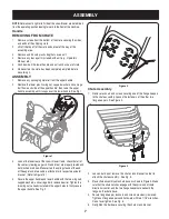
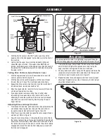
Page 7: ...g auger shift and drive are properly routed and not pinched or kinked Make certain the springs found at the end of the auger and drive cable is attached to its respective actuator bracket Refer to Figure 14 4 Secure the upper handle and lower handle with the two wing nuts cupped washers and carriage bolts removed earlier Tighten the two wing nuts already installed in the upper holes to firmly secu...

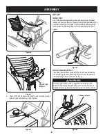
Page 8: ... clean out tool is fastened to the top of the auger housing with a mounting clip and a cable tie at the factory Cut the cable tie before operating the snow thrower See Fig 8 6 Check that the chute cables are properly routed through the cable guide on top of engine shroud See Figure 6 Figure 4 Figure 5 Figure 6 Chute Crank Bracket Figure 7 Figure 8 Clean out Tool WARNING Never use your hands to cle...

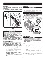
Page 9: ...t cutters are mounted inverted at the factory for shipping purposes 1 Remove the four wing knobs two on each side and carriage bolts Place drift cutter in upright position and re secure See Fig 9 Tire Pressure Pneumatic Tires WARNING Under any circumstance do not exceed manufacturer s recom mended psi Equal tire pressure should be maintained at all times Excessive pressure when seating beads may c...

Page 10: ...king cap In the instance of a threaded oil cap dipstick DO NOT screw the cap dipstick in to check Check the oil by resting the cap dipstick on the threads but not screwing it in 3 Remove the oil filler cap dipstick If the level is low slowly add oil until oil level registers between high H and low L Fig 11 4 Replace and tighten cap dipstick firmly before starting engine NOTE Do not overfill Overfi...

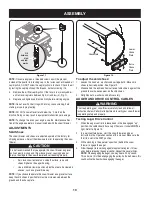
Page 11: ...e appropriate cable and unhook the spring found on the end of the cable from its respective actuator bracket Refer to Figures 14 and 15 2 Slide the spring up the cable to expose the cable coupler threads and lock nut Refer to Figure 15 3 Adjust the lock nut as follows If adjusting the drive cable thread the lock nut outward down the coupler to lengthen the cable and allow the unit to move freely w...

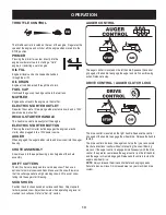
Page 12: ...ontrol closes the choke plate on the carburetor and aids in starting the engine KEY The key is a safety device It must be fully inserted into the ignition in order for the engine to start Remove the key when the snow thrower is not in use IMPORTANT Do not turn the key in an attempt to start the engine Doing so may cause it to break Figure 16 Primer Choke Throttle Starter Handle Oil Drain Electric ...

Page 13: ...RS The drift cutters are designed for use in deep snow Their use is optional for normal snow conditions Maneuver the snow thrower so that the cutters penetrate a high standing snow drift to assist snow falling into the augers for throwing SKID SHOES Position the skid shoes based on surface conditions Adjust upward for hard packed snow Adjust downward when operating on gravel or crushed rock surfac...

Page 14: ...E Be sure to check the engine on a level surface with the engine stopped 1 Remove the oil filler cap dipstick and wipe the dipstick clean 2 Insert the cap dipstick into the oil filler neck and tighten the cap turning clockwise until cap is seated NOTE On some engines a threaded screw cap will be present instead of the quarter turn locking cap In the instance of a threaded oil cap dipstick DO NOT s...

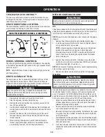
Page 15: ...es overloaded CAUTION To prolong starter life use short starting cycles 5 seconds maximum then wait one minute 6 As the engine warms slowly rotate the choke control to the RUN position If the engine falters restart engine and run with choke at half choke position for a short period of time and then slowly rotate the choke into the RUN position 7 After engine is running disconnect power cord from e...

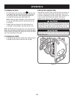
Page 16: ...ng shear pins TO ENGAGE DRIVE 1 With the throttle control in the Fast rabbit position move speed selector lever into one of the six forward F positions or two reverse R positions Select a speed appropriate for the snow conditions and a pace you re comfortable with NOTE When selecting a Drive Speed use the slower speeds until you are comfortable and familiar with the operation of the snow thrower 2...

Page 17: ...ad of the quarter turn locking cap In the instance of a threaded oil cap dipstick DO NOT screw the cap dipstick in to check Check the oil by resting the cap dipstick on the threads but not screwing it in 3 Remove the oil filler cap dipstick If level is low slowly add oil until oil level registers between high H and low L See Figure 18 4 Replace and tighten cap dipstick firmly before starting engin...

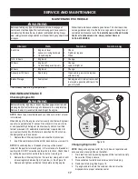
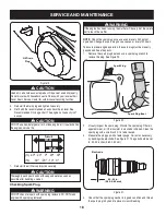
Page 18: ... washer is in good condition and thread the spark plug in by hand to prevent cross threading CAUTION Used oil is a hazardous waste product Dispose of used oil properly Do not discard with household waste Check with your local authori ties or Sears Service Center for safe disposal recycling facilities 5 Reinstall the drain plug and tighten it securely 6 Refill with the recommended oil and check the...

Page 19: ...tighten with a spark plug wrench to compress the washer NOTE When installing a new spark plug tighten 1 2 turn after the spark plug seats to compress the washer When reinstalling a used spark plug tighten 1 8 to 1 4 turn after the spark plug seats to compress the washer CAUTION The spark plug must be tightened securely A loose spark plug can become very hot and can damage the engine CARBURETOR ADJ...

Page 20: ...o wear edges When one side wears out they can be rotated 180 to use the other edge 1 Remove the six carriage bolts washers and hex nuts that secure the two skid shoes to the sides of the auger housing Refer to Figure 24 2 Position the new skid shoes and secure with the carriage bolts and hex nuts Make certain the skid shoes are adjusted to be level Shave Plate 1 Remove the carriage bolts washers a...

Page 21: ...s to adjust the wheel drive control To further check the adjustment proceed as follows 1 With the snow thrower tipped forward be certain to run the fuel tank dry before tipping the unit forward remove the frame cover underneath the snow thrower by removing the self tapping screws See Fig 27 2 Locate the opening between the axle support bracket and the front frame support See Figure 28 Looking thro...

Page 22: ...bracket assembly away from the pulley groove While aligning the pulley slots and adapter posts push the auger pulley fully onto the adapter Refer to Figure 35 Ensure the brake puck of the brake bracket assembly aligns and is fully seated in the pulley groove 4 Loosen the bolt shown in Figure 31 securing the belt keeper bracket and remove the other bolt Push the belt keeper and bracket up off the e...

Page 23: ...lt or out to decrease belt tension NOTE The brake puck must always be firmly seated in the pulley groove when auger control is disengaged IMPORTANT Repeat the Auger Drive Control Test from the As sembly section before operating snow thrower Drive Belt Replacement If not already done remove the auger drive belt from the front pulley of the engine double pulley Refer to Auger Belt Replacement instru...

Page 24: ...the frame cover with self tapping screws Put the snowthrower down to its normal operating position IMPORTANT Repeat the drive control test from the Assembly Assembly section of this manual before operating the snow thrower 5 Using a 3 4 wrench hold the hex shaft and remove the hex bolts and cupped washer and bearing from left side of the frame Refer to Figure 38 6 Holding the friction wheel assemb...

Page 25: ...ffler Touch up any damaged paint and coat other areas that may rust with a light film of oil 5 Store in a clean dry and well ventilated area away from any ap pliance that operates with a flame or pilot light such as a furnace water heater or clothes dryer Also avoid any area with a spark producing electric motor or where power tools are operated 6 If possible also avoid storage areas with high hum...

Page 26: ...park plug wire Tighten all bolts and nuts If vibration continues have unit serviced by an authorized Service Center Loss of power 1 Spark plug wire loose 2 Gas cap vent hole plugged 1 Connect and tighten spark plug wire 2 Remove ice and snow from gas cap Be certain vent hole is clear Unit fails to propel itself 1 Drive control cable in need of adjustment 2 Drive belt loose or damaged 3 Friction wh...

Page 27: ...RAPIDEMENT POUR DÉMARRER PRESSEZ À NOUVEAU L AMORCEUR SI NÉCESSAIRE DÉMARREUR ÉLECTRIQUE NE L UTILISEZ PAS EN CAS DE PLUIE BRANCHEZ LE CORDON ÉLECTRIQUE ET APPUYEZ SUR LE BOUTON DU DÉMARREUR PRESSEZ À NOUVEAU L AMORCEUR SI NÉCESSAIRE 4 5 6 1 INSERT KEY AND SNAP IN PLACE 2 MOVE THROTTLE CONTROL TO THE FAST POSITION 3 MOVE CHOKE CONTROL TO THE CHOKE POSITION PUSH PRIMER 3x 4 ROPE START PULL SLOWLY U...

Page 28: ... 23 36 77 35 30 61 10 47 69 74 34 10 51 71 43 20 68 17 2 37 67 48 4 38 66 38 18 18 6 7 67 3 58 33 32 70 109 111 11 8 58 59 15 14 21 44 22 75 76 45 50 57 64 62 29 31 28 65 60 63 52 24 40 49 23 34 73 27 27 5 55 15 102 100 86 80 92 9 39 57 108 87 103 82 99 98 84 93 78 96 90 107 85 83 97 101 105 89 81 94 91 95 106 79 88 104 23 ...

Page 29: ...ess Chaîne no 41 pas de 1 2 po x 36 maillons 27 713 0286 420 Chain 1 2 pitch x 40 links Endless Chaîne no 420 pas de 1 2 po x 40 maillons 28 913 04015 10T Sprocket 41 x 500 Pignon 10 dents 29 914 0104 Int Cotter Pin 5 16 DIA Goupille fendue 5 16 DIA 30 914 0135 Woodruff Key Clavette 31 914 0388 No 61 Hi Pro Key 3 16 x 5 8 Clavette Hi Pro No 61 3 16 x 5 8 32 716 0104 E ring Bague en E 33 716 0136 R...

Page 30: ...0 x 1 25 85 738 04439 Shoulder Screw 50 x 145 5 16 24 Vis épaulement 0 50 x 0 145 5 16 24 86 710 0347 Hex Hd Cap Scr 3 8 16 x 1 75 Gr 5 Vis à tête hexagonale 3 8 16 x 1 75 Qual 5 87 914 0105 Square Key 3 16 x 1 0 Clavette 3 16 x 1 0 88 926 04012 Push on Nut Écrou poussée 89 931 2531 Belt Cover Courvercle de la courroie 90 732 04308A Torsion Spring 850 x 3 33 Lg Ressort de torsion 0 850 x 3 33 po d...

Page 31: ...31 NOTES ...

Page 32: ...6 54 50 59 11 6 15 9 29 6 45 10 47 72 11 44 16 10 38 36 36 43 37 40 43 23 60 57 56 12 66 52 68 68 51 65 62 60 66 65 42 12 4 5 70 48 6 39 10 3 17 24 14 33 2 49 53 61 63 58 64 55 61 64 16 5 19 7 20 25 18 1 25 20 2 13 6 34 28 32 21 67 8 10 30 69 41 31 43 41 27 71 6 ...

Page 33: ... Mount Support outil de dégagement de la goulotte 25 938 0281 Shoulder Scr 625 Dia x 170 Vis à épaulement dia 0 625 x 0 170 po 26 738 04155 Shear Pin 5 16 18 x 1 75 Goupille de cisaillement 5 16 18 x 1 75 27 741 0192 Flange Bearing Roulement à bride 28 941 04024 Self Aligning Bearing 875 ID Roulement autoaligner 0 875 DI 29 747 0980A Auger Idler Rod Tige de tension de la tarière 30 748 04067A Pull...

Page 34: ...uchon 60 936 0266 Flat Washer 1 5 ID x 2 0 OD x 03 Rondelle plate 1 50 DI x 2 0 DE x 0 03 61 936 0291 Flat Washer 88 ID x 1 4 OD x 125 Rondelle plate 0 88 DI x 1 40 DE x 0 125 62 738 0275 Worm Gear Shaft Support du carter d engrenage 63 741 0184 Thrust Bearing 88 ID x 1 44 OD x 078 Palier à butée 0 88 DI x 1 44 DE x 0 078 64 941 0217 Sleeve Bearing 875 ID Palier à douille 0 875 DI 65 921 0146 Oil ...

Page 35: ...35 NOTES ...

Page 36: ...4 56 59 49 69 47 48 62 29 46 64 23 5 9 13 19 15 63 49 12 14 22 2 25 28 17 7 18 1 20 10 17 13 77 78 64 54 75 39 67 71 72 34 35 31 33 32 76 74 51 58 65 57 52 66 58 50 30 27 53 21 8 40 44 79 79 4 16 11 16 37 42 3 41 39 38 43 45 7 36 3 26 6 68 73 70 55 82 81 80 ...

Page 37: ...e chauffée 25 749 0991 0691 Lower Handle Guidon inférieur 26 790 00329 0637 Chute Crank Brkt Support du bras de goulotte d éjection 27 716 04036 Retainer Ring Bague de retenue 28 725 0157 Cable Tie Attache câble 29 731 06113 Trigger Gachette 30 738 04126 Pin 3 16 Goupille 3 16 31 710 04022 Hex Hd Cap Scr M8 1 25 20 Gr 8 Vis â tête chapeau M8 1 25 20 Qual 8 32 732 04677 Cable Guide Guidage de câble...

Page 38: ... 38 ID x 88 Lg Ressort de compression 0 38 DI x 0 88 po de lg 68 732 04219C Spring Clutch Lock Ressort Verrou d embrayage 69 732 04238 Torsion Spring 8156 x 3038 Ressort de torsion 0 8156 x 0 3038 70 935 0199A Rubber Bumper Pare chocs en caoutchouc 71 936 0267 Flat Washer 38 ID x 87 OD x 09 Rondelle plate 0 38 DI x 0 87 DE x 0 09 72 738 04125 Shoulder Screw 374 Dia x 1 05 Lg Vis à épaulement 0 374...

Page 39: ...REMEDY FOR ANY BREACH OF WARRANTY Customer Responsibilities In additional to complying with all suggested maintenance guidelines and instructions customers obligations shall include but shall not be limited to operating the product in accordance with the owner s manual or any additional instructions or information provided at the time of purchase or in subsequent communications to the purchaser fr...

Page 40: ...02488 Trademarks of Sears Brands Management Corp used under license by Sears Canada Marque déposée MC Marque de commerce de Sears Brands Management Corp utilisée en vertu d une licence de Sears Canada ...

Page 41: ...41 NOTES ...

Page 42: ...31 NOTES ...

Page 43: ...es Pour connaître le no de téléphone du Service des pièces et de l entretien Sears afin de commander les pièces de rechange accessoires et manuels d instructions requis pour effectuer vous même les réparations www sears ca Pour acheter ou demander des renseignements sur un contrat d entretien Sears téléphonez au 1 800 361 6665 de 9 h à 23 h du lundi au vendredi HNE de 9 h à 16 h le samedi For serv...

Page 44: ...e remplacer le produit ou encore d offrir un remboursement complet de son prix d achat à sa seule discrétion CE RECOURS SERA LE SEUL ET UNIQUE RECOURS DONT VOUS DISPOSEREZ EN CAS D INEXÉCUTION QUELLE QU ELLE SOIT DE LA GARANTIE Responsabilités du client En plus d observer toutes les consignes et directives d entretien le client doit s acquitter entre autres des obligations suivantes utiliser le pr...

Page 45: ...la bougie Serrez tous les boulons et écrous Si les vibrations persistent faites vérifier la machine par une station technique agréée Perte de puissance 1 Fil de la bougie desserré 2 Chapeau d échappement d aération bouché 1 Branchez et serrez le fil de la bougie 2 Dégagez la glace et la neige du chapeau Assurez vous de la propreté d aération La souffleuse n avance pas 1 Câble d entraînement mal ré...

Page 46: ... aéré loin de tout appareil à veilleuse ou flamme nue calorifère chauffe eau ou sèche linge Évitez tout endroit où un moteur électrique ou des outils électriques pouvant produire des étincelles sont utilisés 6 Dans la mesure du possible évitez de remiser la souffleuse dans un local très humide qui encouragera la rouille et la corrosion 7 Placez le moteur sur une surface plane car toute inclinaison...

Page 47: ...t dans la rondelle d écartement Assurez vous que la chaîne engage le grand et le petit pignons REMARQUE Si le pignon est tombé de la souffleuse pendant le démontage de l arbre hex alignez le pignon sur la chaîne puis placez le sur l arbre hex Tournez le moyeu hex du pignon vers la roue de frottement en glissant le pignon sur l arbre hex 13 Faites glisser le roulement sur l extrémité gauche de l ar...

Page 48: ...ies en procédant dans l ordre inverse et ajustez la tension avec la poulie de tension 5 Remontez la machine en effectuant les étapes précédentes dans l ordre inverse CHANGEMENT DE LA ROUE DE FROTTEMENT La bague de caoutchouc de la roue de frottement a tendance à s user et devrait être vérifiée périodiquement Remplacez la bague en caoutchouc de la roue de frottement dès l apparition de signes d usu...

Page 49: ...es guides de courroie 9 Tournez la poulie selon le besoin pour aligner les trois fentes avec les taquets de l adaptateur de la poulie puis éloignez le support du frein de l arbre d admission Poussez la poulie de la tarière à fond sur l adaptateur tout en alignant les fentes de la poulie et les taquets de l adaptateur Voir la Figure 35 REMARQUE Si l adaptateur de la poulie a été démonté en même tem...

Page 50: ...comme le montre la Fig 29 3 Enlevez le couvre courroie en plastique sur le devant du moteur en retirant les trois vis autotaraudeuses Voir la Figure 30 4 Desserrez le boulon représenté à la Figure 31 qui maintient le support du guide de courroie puis retirez l autre boulon Éloignez le guide de courroie et le support de la poulie motrice Voir la Figure 31 Courroie d entraînement de la tarière 1 Ret...

Page 51: ... y a suffisamment d espace entre la roue de frottement et la plaque d entraînement à toutes les positions du levier de vitesses Voir la Figure 28 3 Embrayez la commande de l entraînement vérifiez si la roue de frottement touche la plaque d entraînement Voir la Figure 28 4 S il n ya pas de débattement de la roue de friction ou la roue de friction ne pas solidement contact avec la plaque d entraînem...

Page 52: ...es patins sur cette machine ont deux arêtes d usure Quand un côté s use ils peuvent être tourné de 180 à utiliser l autre bord 1 Enlevez les boulons ordinaires les rondelles et les contre écrous à embase qui les maintiennent sur la souffleuse Voir la Figure 24 2 Remontez les nouveaux patins avec les boulons ordinaires les rondelles et les contre écrous à embase Assurez vous que les patins sont aju...

Page 53: ...e maintient Voir la Figure 27 REMARQUE Évitez de répandre de la graisse ou de l huile sur la roue de frottement en caoutchouc et sur la plaque d entraînement en aluminum en lubrifiant l arbre hex Faissant ceci gênera le systême d entraînement de la souffleuse Essuyez toute éclabousure ou excès de l huile 4 Appliquez une légère couche d huile polyvalente toutes saison sur l arbre hex Voir la Figure...

Page 54: ...ver les mains avec de l eau et du savon dès que possible après tout contact 30º 20º 10º 0º 0º 20º 40º 20º 5W 30 0W 30 40º Synthetic L huile usagée est un déchet dangereux dont l élimination est réglementée Ne la jetez pas avec les ordures ménagères Rensei gnez vous auprès des autorités locales ou 1 800 4MY HOME quant aux installations de recyclage agrémentées AVERTISSEMENT ATTENTION L emploi d une...

Page 55: ...artement ou remplacez la bougie Avant le remisage 1 Système de carburant 1 Faire tourner le moteur jusqu à ce qu il s arrête faute de carburant ou d ajouter un additif de l essence au gaz dans le réservoir Sous une charge lourde ou à haute température Suivez le calendrier d entretien ci dessous Le tableau énumère les entretiens et intervalles recommandés Utilisez le carnet d entretien pour enregis...

Page 56: ... à nouveau démarrer avec le volet de départ à moitié fermé pendant quelques instants Puis déplacez lentement le volet de départ à la position Run ARRÊT DU MOTEUR Quand le déblaiement de la neige est terminé laissez tourner le moteur pendant quelques minutes pour sécher toute l humidité qui aurait pu s y accumuler 1 Placez l obturateur à la position Off 2 Retirez la clé de contact Le fait de retire...

Page 57: ...UTILISEZ JAMAIS LE DÉMARREUR ÉLECTRIQUE 1 Branchez le fil électrique dans le démarreur sur le moteur Branchez l autre extrémité du fil dans une prise de courant de 120 volts C A à trois trous mise à la terre dans un endroit bien aéré 2 Placez l obturateur à la position FAST 3 Tournez le bouton du volet de départ à la position VOLET FERMÉ démarrage à froid NOTE Si le moteur est chaud tournez le vol...

Page 58: ...ct et faites démarrer la souffleuse 6 Tenez vous au poste de conduite derrière la souffleuse et embrayez la commande de la tarière pendant quelques secondes pour dégager tout reste de neige ou de glace de la goulotte d éjection POUR FAIRE DÉMARRER LE MOTEU R Huile Cette machine est expédiée avec le plein d huile dans le moteur Vérifiez le niveau d huile avant chaque emploi pour vous assurer qu il ...

Page 59: ...euse de sorte que les barres de coupe pénètrent le haut du banc de neige pour aider à la neige de tomber dans les tarrières pour être soufflée PATINS Positionnez les patins en fonction de la surface de travail Redressez les si la neige est tassée et abaissez les pour travailler sur des surfaces recouvertes de gravier ou de pierre concassée Consultez le chapitre Montage COMMANDE DE LA TARIÈRE Elle ...

Page 60: ...cilite le démarrage du moteur CLÉ DE CONTACT La clé de contact est en fait un dispositif de sécurité Insérez la clé sans la tourner Retirez la clé quand la machine n est pas utilisée REMARQUE Sortez la clé à mi distance pour arrêter le moteur Faisant ainsi la casserez SILENCIEUX L échappement du moteur existe le moteur par le silencieux Figure 16 Amorceur Volet de départ Vidange de l huile Boîte d...

Page 61: ...t facile de la machine quand la commande est enclenchée 4 Pour ajuster le câble de la tarière tournez le contre écrou vers l extérieur vers l extrémité du filet pour allonger le câble selon le besoin et empêcher la rotation de l arbre de la tarière quand la commande est lâchée 5 Accrochez le ressort de chaque câble dans le trou de son support respectif Les deux câbles doivent être accrochés dans l...

Page 62: ...alement immobilisée et qu aucune pièce ne bouge Si la tarière n est pas complètement immobile retournez immédiatement à la position de conduite et arrêtez le moteur Attendez que TOUTES les pièces se soient immobilisées avant d ajuster à nouveau le câble de la tarière Test de la commande l entraînement et du sélecteur de vitesse 1 Arrêtez le moteur et déplacez le sélecteur de vitesse à la position ...

Page 63: ...aut H et bas L de la jauge à huile ou à la limite de débordement dans le cas d un moteur sans jauge à huile Voir la Figure 11 s Vérifier que le capuchon de remplissage de l huile est bien serré 1 Enlevez le capuchon de remplissage de l huile et essuyez la jauge à huile Voir la Figure 11 2 Enfoncez la jauge à huile dans le goulot de remplissage de l huile sans la visser REMARQUE Certains moteurs so...

Page 64: ...in Fuel Recommendations Recommandations concernant le carburant Utilisez une huile automobile sans plomb ou à faible teneur en plomb pour minimiser les dépôts dans la chambre de combustion Une essence contenant jusqu à 10 d éthanol ou 15 de MTBE méthyl ter butyléther peut être utilisée N utilisez jamais un mélange d huile et d essence ou une essence sale Évitez de laisser de la saleté de la poussi...

Page 65: ...util de dégagement de la goulotte L outil de dégagement de la goulotte est fixée avec un support de montage et un attache câble sur l arrière de l habitacle de la tarière à l usine Coupez l attache câble avant de mettre la souffleuse en marche Voir la Figure 8 5 Resserrez les deux écrous qui maintiennent le support de la goulotte 6 Vérifiez que les câbles de la goulotte passent bien dans le guide ...

Page 66: ... vous que les ressorts qui se trouvent à l extrémité des câbles de la tarière et de la transmission sont bien accrochés à leurs supports respectifs Voir la Figure 14 4 Attachez les guidons supérieur et inférieur avec les boutons les rondelles creuses et les boulons ordinaires enlevés précédem ment Serrez les boutons déjà en place sur les trous supérieurs et fixez les guidons fermement Voir la Figu...

Page 67: ...e Cet outil a été fixé avec un attache câble à l usine Coupez l attache câble avant de mettre la souffleuse en marche AVERTISSEMENT Ne vous servez jamais de vos mains pour dégager une obstruction dans la goulotte Arrêtez le moteur et restez derrière les guidons jusqu à ce que toutes les pièces se soient arrêtées avant de vous servir de l outil de dégagement pour nettoyer la goulotte Outil de dégag...

Page 68: ...TS PROJETÉS Cette machine peut ramasser et projeter des objets ce qui peut causer des blessures graves AVERTISSEMENT L ESSENCE EST UN PRODUIT INFLAMMABLE Laissez le moteur refroidir pendant au moins deux minutes avant de refaire le plein AVERTISSEMENT MONOXYDE DE CARBONE Ne faites jamais fonctionner un moteur à l intérieur ou dans un bâtiment mal ventilé Les gaz d échappement contiennent du monoxy...

Page 69: ...arrêtez le moteur Attendez que la tarière turbine se soit complètement immobilisée Débranchez le fil de la bougie et mettez le à la terre pour empêcher tout démarrage accidentel pendant le nettoyage la réparation ou l examen de la machine 3 Vérifiez régulièrement que les boulons et vis sont bien serrés et maintenez la machine en bon état de marche Examinez soigneusement la machine pour vous assure...

Page 70: ...ais le capuchon d essence et n ajoutez pas d essence pendant que le moteur tourne e Laissez le moteur refroidir pendant au moins deux minutes avant de faire le plein f Ne faites jamais déborder le réservoir Laissez un espace d un demi pouce environ pour permettre l expansion du carburant g Resserrez bien le capuchon d essence h En cas de débordement essuyez toute éclaboussure sur le moteur et la m...

Page 71: ...emisage hors saison 27 Dépannage 28 Pièces détachées voir la page 28 de la version anglaise de cette notice d utilsation Garantie 29 1 800 4 MY HOME 30 Numéro de modèle Numéro de série Date d achat Inscrivez le numéro de modèle le numéro de série et la date d achat ci dessus TABLE DES MATIÈRES NUMÉRO DE MODÈLE ...

Page 72: ...rs Canada Inc 290 Yonge Street Toronto On M5B 2C3 Visit our web site sears ca 6 29 2012 769 08250 ATTENTION Lisez attentivement les règles de sécurité et les instructions avant de mettre la machine en marche Notice d utilisation s 3 52 4 s 4 s 54 3 4 s 42 4 s 0 3 4 3 ...

Reviews: