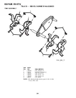
Craftsman 944.628653 Owner'S Manual Download Page 9

9

OPERATION

Fig. 10

BREAKING IN YOUR TILLER

Break-in your belt(s), pulleys and tine control before you 
actually begin tilling.
• 

Start engine, tip tines off ground by pressing handles 
down and engage tine control to start tine rotation. 
Allow tines to rotate for five minutes.

• 

Check tine operation and adjust if necessary.  See “TINE 
OPERATION CHECK” in the Service and Ad just ments 
sec tion of this manual.

TILLING HINTS   

CAUTION:  Until you are accustomed 
to handling your tiller, start ac tu al field 
use with throttle in slow position. 

To help tiller  move forward, lift up the handles slightly (thus 
lifting depth stake out of ground). To slow down the tiller, 
press down on handles.

If you are straining or tiller is shaking, the wheels and depth 
stake are not  set properly in the soil being tilled. The proper 
setting of the wheels and depth stake is through trial and 
error and depends upon the soil con di tion.  (The harder or 
wetter the ground, the slower the engine and tine speed 
needed. Under these poor con di tions, at fast speed the 
tiller will run and jump over the ground). 

 A properly adjusted tiller will dig with little effort from the 
operator.
• 

Tilling is digging into, turning over, and breaking up 
packed soil before planting.  Loose, unpacked soil 
helps root growth. Best tilling depth is 4"-6".  A tiller 
will also clear the soil of unwanted vege ta tion. The 
de com po si tion of this vegetable mat ter en rich es the 
soil.  De pend ing on the climate (rain fall and wind), it 
may be advisable to till the soil at the end of the grow-
ing season to further condition the soil.

• 

Soil conditions are important for proper tilling. Tines will 
not readily penetrate dry, hard soil which may con trib ute 
to excessive bounce and difficult handling of your tiller. 
Hard soil should be mois tened before tilling; however, 
extremely wet soil will “ball-up” or clump during tilling. 
Wait until the soil is less wet in order to achieve the 
best results. When tilling in the fall, remove vines and 
long grass to prevent them from wrapping around the 
tine shaft and slowing your tilling operation.

3

2

1

5

4

6

7

CULTIVATING

Cultivating is destroying the weeds between rows to pre-
 vent them from robbing nourishment and moisture from the 
plants. At the same time, breaking up the upper layer of 
soil crust will help retain moisture in the soil. Best digging 
depth is 1"-3".
• 

You will probably not need to use the depth stake. Begin 
by tipping the depth stake forward until it is held by the 
stake spring.

• 

Cultivate up and down the rows at a speed which will 
allow tines to uproot weeds and leave the ground in 
rough con di tion, promoting no fur ther growth of weeds 
and grass (See Fig. 10).

• 

You will find tilling much easier if you leave a row 
untilled between passes. Then go back between tilled 
rows. (See Fig. 8) There are two reasons for doing 
this. First, wide turns are much easier to negotiate than 
about-faces. Sec ond, the tiller won’t be pulling  itself, 
and you, toward the row next to it.

• 

Set depth stake and wheel height for shallow tilling 
when working extremely hard soil or sod. Then work 
across the first cuts at normal depth.

Fig. 9

Summary of Contents for 944.628653

Page 1: ...ules and Instructions Before Operating This Equipment MODEL NO 944 628653 OWNER S MANUAL Assembly Operation Maintenance Service and Adjustments Repair Parts 900 SERIES 24 INCH TINE WIDTH Sears Canada Inc Toronto Ontario M5B 2B8 434930 Rev 1 ...

Page 2: ... the controls and the proper use of the equipment Know how to stop the unit and disengage the controls quickly Never allow children to operate the equipment Never allow adults to operate the equipment without proper instruction Keep the area of operation clear of all persons par ticularly small children and pets PREPARATION Thoroughly inspect the area where the equipment is to be used and remove a...

Page 3: ...NIT IS EQUIPPED WITH AN INTERNAL COMBUSTION ENGINE AND SHOULD NOT BE USED ON OR NEAR ANY UNIMPROVED FOREST COVERED BRUSH COVERED OR GRASS COVERED LAND UNLESS THE ENGINE S EXHAUST SYSTEM IS EQUIPPED WITH A SPARK ARRESTER MEETING APPLICABLE LOCAL OR STATE LAWS IF ANY IF A SPARK ARRESTER IS USED IT SHOULD BE MAINTAINED IN EFFECTIVE WORKING ORDER BY THE OPERATOR SEE YOUR SEARS AUTHORIZED SERVICE CENTR...

Page 4: ...tion standing behind tiller handles Your new tiller has been assembled at the factory with exception of those parts left unassembled for shipping purposes To ensure safe and proper operation of your tiller all parts and hardware you assemble must be tightened securely Use the correct tools as necessary to insure proper tightness ASSEMBLY 2 Flange Locknuts 5 16 18 UNC 2 Lock Washer 5 16 2 Hex Nut 5...

Page 5: ...olumn onto handle mount Remove all packing from carton Secure handle column using two 2 carriage bolts and two 2 flange locknuts Tighten securely Cut away carton Route tine control cable s through plastic cable clip on handle mount NOTE Cables must not touch the muffler Cut cable ties securing tiller to skid Remove tiller from skid by pulling backwards Remove screws securing depth stake to skid an...

Page 6: ...or RECOIL STARTER HANDLE Used to start the engine THROTTLE CONTROL Used to control engine speed KNOW YOUR TILLER READ THIS OWNER S MANUAL AND SAFETY RULES BEFORE OPERATING YOUR TILLER Compare the illustrations with your tiller to familiarize yourself with the location of various controls and adjustments Save this manual for future reference These symbols may appear on your Tiller or in literature ...

Page 7: ...6 TO TRANSPORT CAUTION Before lifting or trans porting allow tiller engine and muffler to cool Disconnect spark plug wire Drain gasoline from fuel tank AROUND THE YARD Tip depth stake forward until it is held by the stake spring Push tiller handles down raising tines off the ground Push or pull tiller to desired location AROUND TOWN Disconnect spark plug wire Drain fuel tank Transport in upright p...

Page 8: ...ing engine When starting engine for the first time or if engine has run out of fuel it will take extra pulls of the recoil starter to move fuel from the tank to the engine Make sure spark plug wire is properly connected Place throttle control in FAST position Move choke control to full CHOKE position Grasp recoil starter handle with one hand and grasp tiller handle with other hand Pull rope out sl...

Page 9: ...ainfall and wind it may be advisable to till the soil at the end of the grow ing season to further condition the soil Soilconditionsareimportantforpropertilling Tineswill notreadilypenetratedry hardsoilwhichmaycontribute to excessive bounce and difficult handling of your tiller Hard soil should be moistened before tilling however extremely wet soil will ball up or clump during tilling Wait until t...

Page 10: ...proper air fuel mixture and help your engine run better and last longer BEFORE EACH USE Check engine oil level Check tine operation Check for loose fasteners LUBRICATION Keep unit well lubricated See LUBRICATION CHART LUBRICATION CHART 4 3 5 ª ª 4 3 3ª9 5ª 0 4 2 5 2ª3 26 HECKª NGINEª ILª EVEL HANGEª NGINEª IL ILª0IVOTª0OINTS NSPECTª IRª3CREEN NSPECTª3PARKª RRESTERª ª UFFLER LEANªORª2EPLACEª IRª LE...

Page 11: ...fins as contact may cause burns TO CHANGE ENGINE OIL See Figs 11 and 12 Determine temperature range expected before oil change All oil must meet API service classification SF SJ Be sure tiller is on level surface Oil will drain more freely when warm Catch oil in a suitable container Remove drain plug Tip tiller forward to drain oil After oil has drained completely replace oil drain plug and tighte...

Page 12: ...K PLUG Replace spark plugs at the beginning of each tilling sea son or after every 50 hours of use whichever comes first Spark plug type and gap setting are shown in PRODUCT SPECIFICATIONS on page 3 of this manual TRANSMISSION Once a season lubricate the right hand side gear case grease fitting with 1 oz of EP 1 Grease CLEANING Do not clean your tiller when the engine and transmission are hot We d...

Page 13: ...L TILLING See Fig 16 Assemble holes A in tine hubs to holes B in tine shaft tine_4 OUTER TINE HAIRPIN CLIP A B A B Fig 16 INNER TINE CLEVIS PIN NOTE When reassembling outer tines be sure right tine assembly marked R and left tine assembly marked L are mounted to correct side of tine shaft TINE OPERATION CHECK See Fig 18 WARNING Disconnectsparkplugwire fromsparkplugtopreventstartingwhile checking t...

Page 14: ... guard must be removed to service belt See TO RE MOVE BELT GUARD in this section of manual BELT REMOVAL Remove V belt from transmission pulley first and then from engine pulley BELT REPLACEMENT Install new V belt to engine pulley first then to trans mission pulley Be sure belt is positioned on inside groove of both pulleys inside all belt guides and rests on idler pulley CHECK TINE OPERATION See T...

Page 15: ...Inspect and replace belts if necessary See belt re placement instructions in the Service and Adjustments section of this manual Lubricate as shown in the Maintenance section of this manual Be sure that all nuts bolts and screws are securely fastened Inspect moving parts for damage breakage and wear Replace if necessary Touch up all rusted or chipped paint surfaces sand lightly before painting ENGI...

Page 16: ...ill and clean carburetor 6 Stale or dirty fuel 6 Empty fuel tank and refill with fresh gasoline 7 Water in fuel 7 Empty fuel tank and carburetor and refill tank with fresh gasoline 8 Clogged fuel tank 8 Remove fuel tank and clean 9 Spark plug wire loose 9 Connect and tighten spark plug wire 10 Dirty engine air screen 10 Clean engine air screen 11 Dirty clogged muffler 11 Clean replace muffler 12 C...

Page 17: ...07 Bolt RH SQNK 5 16 18 x 3 4 14 181476 Assembly Panel and Tube 19 188532 Lever Control Tine 20 188555 Pin Pivot 29 12000059 Retainer Ring 35 72010520 Bolt 5 16 18 x 2 1 2 36 73970500 Locknut Flange 5 16 18 unc 38 431332 Assembly Handle Column 39 181580 Clip NOTE All component dimensions given in U S inches 1 inch 25 4 mm KEY PART NO NO DESCRIPTION ...

Page 18: ...8 139155 Spacer Split 9 165768X613 Guard Belt 10 109227X Pad Idler 11 9484R Clip Cable 12 9180R V Belt 13 12000028 Ring Retainer 14 151223 Sheave Transmisison 16 12000036 Ring Klip 17 STD541237 Nut Hex Jam 3 8 16 18 161806 Pulley Idler 19 175377 Arm Idler 20 STD523712 Bolt Hex Head 3 8 16 x 1 1 4 21 106968X Shaft Idler Arm 25 73350500 Nut Hex Jam 5 16 18 KEY PART NO NO DESCRIPTION NOTE All compone...

Page 19: ...pth Stake R H 9 122233X Stake Depth 10 326J Pin Clevis 11 74780628 Bolt Hex 3 8 16 x 1 3 4 13 1951J Support Depth Stake L H 15 5388J Spring Stake 16 121117X Bolt Shoulder 17 193851X613 Wheel 19 9190R Bracket Wheel 20 STD541437 Locknut Crown 3 8 16 21 74760516 Bolt Hex Head 5 16 18 x 1 22 STD541431 Locknut w insert 5 16 18 24 73970500 Nut Lock 5 16 18 25 19171416 Washer 17 32 x 7 8 x16 Ga KEY PART ...

Page 20: ...5 4 mm REPAIR PARTS TILLER MODEL NUMBER 944 628653 TINE ASSEMBLY 1 156926 Tine Outer R H 2 3146R Retainer Spring Zinc 3 156924 Tine Inner R H 4 156923 Tine Inner L H 5 156925 Tine Outer L H 6 4929H Pin Clevis KEY PART NO NO DESCRIPTION 3 1 6 4 5 6 2 2 tine_ipb_3 ...

Page 21: ...ngine L H 11 187912 Bolt Shoulder 5 16 18 unc x 2 5 12 151222 Transmission 14 9173R Spacer Split 15 73970500 Nut Lock Hex Flange 5 16 18 unc 16 19091412 Washer 9 32 x 7 8 x 12 Ga 17 19092016 Washer 9 32 x 1 1 4 x 16 Ga 18 STD551125 Washer Lock 1 4 19 74610412 Bolt Hex 1 4 28 x 3 4 Gr 5 20 Engine See Breakdown 121002 1380 B8 KEY PART NO NO DESCRIPTION NOTE All component dimensions given in U S inch...

Page 22: ...425979 Decal Logo 3 435125 Decal Engine 4 425981 Decal Tine Shield 5 419833 Decal Cntrl Pnl Inst 6 110614X Decal Hand Placement 8 422972 Decal Tine Shield Warning 11 120076X Decal Warning Rotating Tines 12 425501 Decal Console 434930 Manual Owner s English 434931 Manual Owner s French 5 8 11 3 6 1 12 2 4 ...

Page 23: ...23 REPAIR PARTS TILLER MODEL NUMBER 944 628653 ENGINE BRIGGS MODEL NUMBER 121002 1380 B8 2 0 2 5 3 24 2 0 4 0 2 4 2 3 5 ...

Page 24: ...24 REPAIR PARTS TILLER MODEL NUMBER 944 628653 ENGINE BRIGGS MODEL NUMBER 121002 1380 B8 ...

Page 25: ...25 REPAIR PARTS TILLER MODEL NUMBER 944 628653 ENGINE BRIGGS MODEL NUMBER 121002 1380 B8 6 6 3 4 3 4 2 52 4 2 6 2 5 4 3 4 3 4 33 3 ...

Page 26: ...Welch 130 691181 Valve Throttle 133 398187 Float Carburetor 134 398188 Kit Needle Seat 137 693981 Gasket Float Bowl 146 690979 Key Timing 155 797442 Plate Cylinder Head 161 790631 Base Air Cleaner 163 696024 Gasket Air Cleaner 186 692317 Hose Connector 187 791766 Line Fuel Cut to Required Length 187A 791867 Line Fuel Formed 188 699479 Screw Control Bracket 190 699220 Screw Fuel Tank 192 797440 Adj...

Page 27: ...4 699480 Screw Rocker Cover Bottom 914A 797444 Screw Rocker Cover 951 790630 Lever Choke 957 795027 Cap Fuel Tank 958 698180 Valve Fuel Shut Off 968 791082 Cover Air Cleaner 972 697779 Tank Fuel 975 790559 Bowl Fuel 993 694088 Gasket Cylinder Head Plate 1005 692592 Fan Flywheel 1022 691890 Gasket Rocker Cover 1023 499924 Cover Rocker 1026 790287 Rod Push 1029 797443 Arm Rocker 1034 691343 Guide Pu...

Page 28: ...n SUCH REMEDY SHALL BE YOUR SOLE AND EXCLUSIVE REMEDY FOR ANY BREACH OF WARRANTY CUSTOMER RESPONSIBILITIES In additional to complying with all suggested maintenance guidelines and instructions customers obligations shall include but shall not be limited to operating the product in accordance with the owner s manual or any additional instructions or information provided at the time of purchase or i...

Page 29: ...29 SERVICE NOTES ...

Page 30: ...30 SERVICE NOTES ...

Page 31: ...31 SERVICE NOTES ...

Page 32: ...02488 03 09 10 JA Printed in the U S A ...

Reviews: