


5
ASSEMBLY
de
pth_
st
ak
e_
4
Hex Bolts, Lock Wash ers, and hex Nuts
Support Bolt
Depth Stake Support
Engine Bracket Halves
Nut “A”
Depth
Stake
Stake Spring
Fig. 2
INSTALL DEPTH STAKE ASSEMBLY
(See Fig. 3)
•
Loosen nut “A”.
•
Insert stake support between engine bracket halves
with stake spring down.
•
Bolt stake support to engine brackets with bolts, lock
washers and nuts. Tighten se curely. Tighten nut “A”.
•
Depth stake must move freely. If it does not, loosen
support bolt.
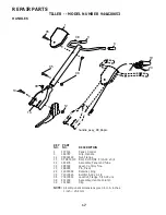
UNPACK CARTON & INSTALL HANDLE
(See Fig. 2)
CAUTION: Be careful of exposed
sta ples when handling or disposing of
cartoning material.
IMPORTANT:
WHEN UNPACKING AND AS
SEM BLING
TILLER, BE CAREFUL NOT TO STRETCH OR KINK
CABLE(S).
•
Cut cable ties securing handle column.
•
Route cable(s) as shown and slide handle column onto
handle mount.
•
Remove all packing from carton.
•
Secure handle column using two (2) carriage bolts and
two (2) flange locknuts. Tighten se cure ly.
•
Cut away carton.
•
Route tine control cable(s) through plas tic cable clip
on handle mount.
NOTE: Cables must not touch the muffler.
•
Cut cable ties securing tiller to skid. Re move tiller from
skid by pulling backwards.
•
Remove screws securing depth stake to skid and
discard the screws.
HANDLE HEIGHT
•
Handle height may be adjusted to better suit operator.
(See “HANDLE HEIGHT” in the Service and Ad just ments
section of this manual).
TILLING WIDTH
•
Tilling width may be adjusted to better handle your
tilling con di tions (See “TINE ARRANGEMENT” in the
Ser vice and Adjustments section of this manual).
TINE OPERATION
•
Check tine operation before first use. (See “TINE
OPERATION CHECK” in the Service and Adjustments
section of this manual).
Fig. 3
TINE
CONTROL
CABLE
TINE CON TROL
HAN DLE
MOUNT
HANDLE
COLUMN
FLANGE
LOCKNUT
CARRIAGE
BOLT


