background image

7

SPEED AND WIRING

The no-load speed of this tool is approximately 3,000 
sfpm.


This speed is not constant and decreases under 

a load or with lower voltage. For voltage, the wiring in a 
shop is as important as the motor’s horsepower rating. A 
line intended only for lights cannot properly carry a power 
tool motor. Wire that is heavy enough for a short distance 
will be too light for a greater distance. A line that can
support one power tool may not be able to support two 
or three tools.

GROUNDING INSTRUCTIONS

In the event of a malfunction or breakdown, grounding 
provides a path of least resistance for electric current to 
reduce the risk of electric shock. This tool is equipped with 
an electric cord having an equipment-groundIng conduc-
tor and a grounding plug. The plug must be plugged into a 
matching outlet that is properly installed and grounded in 
accordance with all local codes and ordinances.
Do not modify the plug provided. If it will not fit the outlet, 
have the proper outlet installed by a qualified electrician. 
Improper connection of the equipment-grounding con-
ductor can result in a risk of electric shock. The conductor 
with insulation having an outer surface that is green with or 
without yellow stripes is the equipment-grounding 
conductor. If repair or replacement of the electric cord or 
plug is necessary, do not connect the equipment-
grounding conductor to a live terminal.
Check with a qualified electrician or service personnel if 
the grounding instructions are not completely understood, 
or if in doubt as to whether the tool is properly grounded.
Repair or replace a damaged or worn cord immediately.
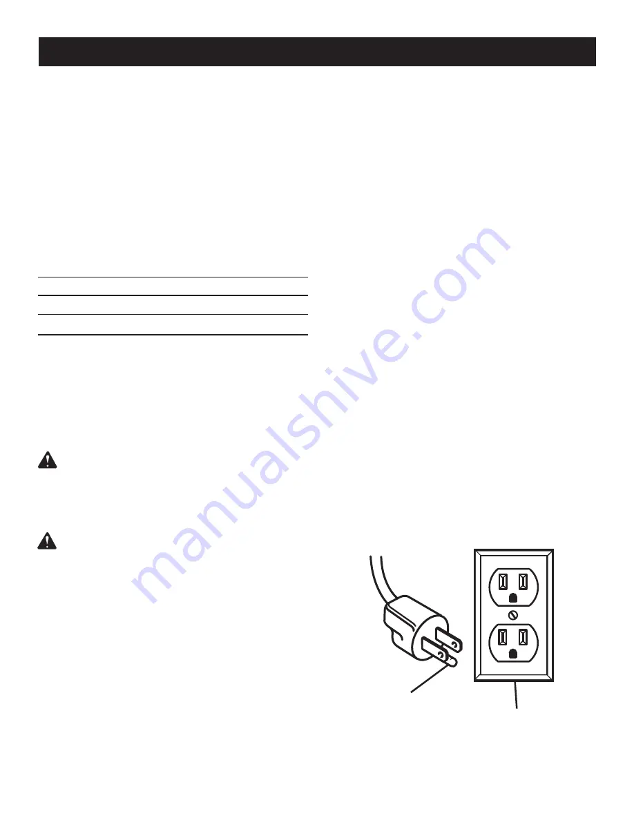
This tool is intended for use on a circuit that has an outlet 
like the one shown in figure 1. It also has a grounding pin 
like the one shown.

ELECTRICAL

Fig. 1 

GROUNDING 

PIN

COVER OF GROUNDED 

OUTLET BOX

EXTENSION CORDS

Use only 3-wire extension cords that have 3-prong 
grounding plugs and 3-pole receptacles that accept the 
tool’s plug. When using a power tool at a considerable 
distance from the power source, use an extension cord 
heavy enough to carry the current that the tool will draw. 
An undersized extension cord will cause a drop in line 
voltage, resulting in a loss of power and causing the motor 
to overheat. Use the chart provided below to determine 
the minimum wire size required in an extension cord. Only 
round jacketed cords listed by Underwriter’s Laboratories 
(UL) should be used.

**Ampere rating  (on tool faceplate)
                        0-2.0          2.1-3.4        3.5-5.0       5.1-7.0      7.1-12.0   12.1-16.0

Cord Length                Wire Size (A.W.G.)

    25'         16          16          16         16         14        14

    50'         16          16          16         14         14        12

  100'         16          16          14         12         10        —

**Used on 12 gauge - 20 amp circuit.

NOTE:

 AWG = American Wire Gauge

When working with the tool outdoors, use an extension 
cord that is designed for outside use. This is indicated by 
the letters “WA” on the cord’s jacket.
Before using an extension cord, inspect it for loose or 
exposed wires and cut or worn insulation.

WARNING:

 Keep the extension cord clear of the 

working area. Position the cord so that it will not get 
caught on lumber, tools or other obstructions while 
you are working with a power tool. Failure to do so 
can result in serious personal injury.

WARNING:

 Check extension cords before each 

use. If damaged replace immediately. Never use tool 
with a damaged cord since touching the damaged 
area could cause electrical shock resulting in serious 
injury.

ELECTRICAL CONNECTION

This tool is powered by a precision built electric motor. 
It should be connected to a 

power supply that is 120 

volts, 60 Hz, AC only (normal household current). 

Do 

not operate this tool on direct current (DC). A substantial 
voltage drop will cause a loss of power and the motor will 
overheat. If the saw does not operate when plugged into 
an outlet, double check the power supply.

Summary of Contents for 315.214770

Page 1: ...educe the risk of injury the user must read and understand the operator s manual before using this product Customer Help Line 1 800 932 3188 Sears Roebuck and Co 3333 Beverly Rd Hoffman Estates IL 60179 USA Visit the Craftsman web page www sears com craftsman 983000 577 8 04 Save this manual for future reference ...

Page 2: ...e date of purchase RETURN IT TO THE NEAREST SEARS STORE OR SEARS SERVICE CENTER IN THE UNITED STATES and Sears will repair it free of charge If this CRAFTSMAN tool is used for commercial or rental purposes this warranty applies for only 90 days from the date of purchase This warranty gives you specific legal rights and you may also have other rights which vary from state to state Sears Roebuck and...

Page 3: ...mps or a vise to hold work when practical It s safer than using your hand and it frees both hands to operate tool n DO NOT OVERREACH Keep proper footing and balance at all times n MAINTAIN TOOLS WITH CARE Keep tools sharp and clean for best and safest performance Follow instructions for lubricating and changing accessories n DISCONNECT ALL TOOLS When not in use before servicing or when changing at...

Page 4: ...nplug the saw and re move the switch key n KEEP BLADES CLEAN SHARP AND WITH SUFFI CIENT SET Sharp blades minimize stalling and kick backs n ALWAYS TURN OFF SAW before disconnecting it to avoid accidental starting when reconnecting to a power source n DO NOT OPERATE THIS TOOL WHILE UNDER THE INFLUENCE OF DRUGS ALCOHOL OR ANY MEDI CATION n STAY ALERT AND EXERCISE CONTROL Watch what you are doing and...

Page 5: ...njury user must read and understand operator s manual before using this product Eye Protection Always wear safety goggles or safety glasses with side shields and a full face shield when operating this product Precautions that involve your safety Failure to keep your hands away from the blade will result in serious personal injury Failure to keep your hands away from the blade will result in seriou...

Page 6: ...ginning power tool operation always wear safety goggles or safety glasses with side shields and a full face shield when needed We recommend Wide Vision Safety Mask for use over eyeglasses or standard safety glasses with side shields Always use eye protection which is marked to comply with ANSI Z87 1 WARNING SAVE THESE INSTRUCTIONS SYMBOL SIGNAL MEANING DANGER Indicates an imminently hazardous situ...

Page 7: ... ELECTRICAL Fig 1 GROUNDING PIN COVER OF GROUNDED OUTLET BOX EXTENSION CORDS Use only 3 wire extension cords that have 3 prong grounding plugs and 3 pole receptacles that accept the tool s plug When using a power tool at a considerable distance from the power source use an extension cord heavy enough to carry the current that the tool will draw An undersized extension cord will cause a drop in lin...

Page 8: ...e or Material The item on which the operation is being done Worktable Surface where the workpiece rests while performing a cutting drilling planing or sanding operation Anti Kickback Pawls radial arm and table saws A device which when properly installed and maintained is designed to stop the workpiece from being kicked back toward the front of the saw during a ripping operation Arbor The shaft on ...

Page 9: ...N KNOB LATCH DUST EXHAUST PORT AND ADAPTER BLADE GUARD 0 15 45 TRACKING KNOB ANGLE ADJUSTMENT KNOB FEATURES PRODUCT SPECIFICATIONS Blade Width 1 8 in to 3 8 in Blade Length 59 1 4 in Frame to Blade Capacity 9 in Cutting Thickness Capacity 3 1 8 in Table Size 11 3 8 in x 11 3 8 in Table Tilt 0 45 Input 120 Volt 60Hz AC Only 2 3 Amps No Load Speed 3 000 SFPM Overall Dimensions 19 1 2 in x 12 1 2 in ...

Page 10: ... the wheels Tracking View Window The tracking view window makes tracking adjustments easier to see KNOW YOUR BAND SAW See Figure 2 Before attempting to use this product familiarize yourself with all operating features and safety rules Angle Adjustment Knob Tilts the saw table for bevel cutting Blade Guard Protects the operator from coming in contact with the blade Blade Guide Support Helps keep th...

Page 11: ...E HEX KEY 3 mm 4 mm 5 mm The following tools not included are needed for checking adjustments of the saw or for installing the blade TOOLS NEEDED PHILLIPS SCREWDRIVER COMBINATION SQUARE ADJUSTABLE WRENCH SAW TABLE TABLE LOCK HANDLE WASHER 30 45 60 75 90 75 6 0 45 30 Table Lock Handle 1 Washer 1 Saw Blades 2 Operator s Manual not shown 1 Fig 3 SAW BLADES ...

Page 12: ... use with this tool Any such alteration or modification is misuse and could result in a hazardous condition leading to possible serious personal injury WARNING Do not connect to power supply until assembly is complete Failure to comply could result in accidental starting and possible serious personal injury MOUNTING THE SAW TABLE See Figures 5 6 WARNING Always make sure the band saw is securely mo...

Page 13: ... hex nuts not included NOTE All bolts should be inserted from the top Install the lock washers and hex nuts from the underside of the bench Supporting surface where band saw is mounted should be examined carefully after mounting to insure that no movement during use can result If any tipping or walk ing is noted secure workbench or support surface before beginning cutting operation ON REM OVE TOLO...

Page 14: ...ilure to heed this warning could result in a serious eye injury n Loosen and remove the wing nut and table aligning bolt from the saw table n Remove the saw table before opening the front cover of the saw housing n Loosen the two set screws that hold the blade guard in place using the 4 mm hex key provided then remove the blade guard n Turn the lock lever counterclockwise to unlock the blade guide...

Page 15: ...ust blade tension properly before making tracking adjustments Check that the blade guides are not interfering with the blade To Adjust n Open the front cover by releasing the upper and lower latches Watch the blade s position on the upper tire through the tracking view window as by hand you slowly turn the upper wheel clockwise If the blade moves away from the center of the tire the tracking must ...

Page 16: ...l screws securely n Replace the blade guard once the saw table has been squared BLADE GUIDE ASSEMBLY ZERO STOP SET SCREW Fig 13 3 MAX IMUM C UT T ING C AP AC IT Y ON REMOV E TOLOCK O SMALL COMBINATION SQUARE SAW BLADE Fig 12 BLADE ON WHEEL BLADE TENSION KNOB BLADE TRACKING KNOB TRACKING VIEW WINDOW If the blade has moved left or right of center n Turn the blade tracking knob clockwise if blade has...

Page 17: ...PPORT AND BLADE GUIDES See Figures 14 16 WARNING Never operate saw without blade guard secured in place To do so could result in possible serious personal injury The upper and lower blade guides and thrust bearings support the band saw blade during cutting operations The adjustment of the guides and bearings should be checked whenever a different blade is installed To Adjust Thrust Bearings The th...

Page 18: ...the saw off remove the switch key and unplug the saw Do not restart until locating and correcting the prob lem CUTTING PROCEDURES n Hold the workpiece firmly against the saw table n Use gentle pressure and both hands when feeding the work into the blade Do not force the work allow the blade to cut n The smallest diameter circle that can be cut is deter mined by blade width A 1 4 in wide blade will...

Page 19: ... the same time Do not try to turn the workpiece while engaged in the blade without pushing it the workpiece could bind or twist the blade REMOVING JAMMED MATERIAL Never remove jammed cutoff pieces until the blade has come to a full and complete stop n Place the switch in the OFF position remove the switch key from the switch assembly n Unplug the saw from the power source before remov ing jammed m...

Page 20: ...ABLE Fig 17 ON ON REMOVE TOLOCK O 30 45 60 75 90 75 60 45 30 OFF SWITCH KEY n Place the switch in the OFF position remove the switch key from the switch assembly Store key in a safe place TILTING THE TABLE See Figure 18 n Loosen the table lock handle slightly n Turn the angle adjustment knob tilting the saw table toward the front of the saw housing until it reaches the desired angle n Using the sc...

Page 21: ...n Remove sawdust from the inside frequently n Do not allow pitch to accumulate on the saw table blade guides or thrust bearings Clean them with gum and pitch remover n Apply a thin coat of automobile type wax to the saw table s top so the wood slides easily while cutting LUBRICATION All of the bearings in this tool are lubricated with a suffi cient amount of high grade lubricant for the life of th...

Page 22: ...housing n Retighten using the washer and screw DRIVE BELT See Figures 22 23 WARNING To prevent accidental starting that could cause possible serious personal injury turn off the saw remove the switch key and unplug the saw before working on the band saw Due to wear or breakage the drive belt may need to be replaced The drive belt is located behind the lower wheel of the band saw n Unplug the band ...

Page 23: ...ting 3 Thrust bearings scarred or not rotating 1 Adjust tension See Adjustments section Adjusting Blade Tension 2 Use correct cutting technique See section Operation 3 Replace the thrust bearings See Adjusting Thrust Bearings Saw is noisy when running 1 Too much blade tension 2 Blade guides and bearings are in contact with the blade 1 Adjust tension See Adjustments section Adjusting Blade Tension ...

Page 24: ...24 NOTES NOTES ...

Page 25: ...25 FIGURE A CRAFTSMAN BAND SAW MODEL NO 315 214770 1 2 3 4 5 6 7 8 7 9 10 11 12 13 14 15 16 17 18 19 ...

Page 26: ...90105900 Table 290 mm x 290 mm x 22 mm 1 2 089120100014 Throat Plate 38 mm x 38 mm 1 3 089120100805 Miter Gauge Assembly 1 4 089120100018 Hex Screw M5 x 25 mm 1 5 089120100026 Washer M5 x 9 STD851005 1 6 089120100019 Wing Nut M5 1 7 BS90105800 Nut M6 2 8 BS90108200 Bolt M6 1 9 089120100900 Angle Scale Label 1 10 BS90105100 Bolt M6 x 16 mm 4 11 BS90105200 Spring Washer M6 STD852006 4 12 BS90105300 ...

Page 27: ...housing Always mention the model number in all correspondence regarding your band saw or when ordering repair parts Key Part No Number Description Qty 1 BS90106800 Motor Assembly 1 2 BS90104800 Washer M8 x 22 STD851008 2 3 BS90106700 Bolt M8 x 25 mm 2 4 BS90108000 Power Cord SJP18AWG 3c 6ft 1 5 BS90103900 Screw M4 x 10 mm Flat Hd 2 6 089120100024 Fixing Plate 1 7 BS90108100 Strain Relief 2 8 08912...

Page 28: ...our band saw or when ordering repair parts Key Part No Number Description Qty 1 089120100006 Hex Socket Head Screw M5 x 8 mm 2 2 BS90102400 Blade Guide 1 3 BS90101700 Gear 1 4 BS90101600 Bracket 1 5 BS90101500 Carriage Bolt M6 x 66 mm 1 6 BS90101900 Pin 1 7 BS90102000 Guide B 1 8 089120100032 Hex Socket Head Screw M5 x 15 mm 1 9 BS90102200 Guide A 1 10 089120100005 Hex Socket Head Screw M5 x 12 mm...

Page 29: ...NO 315 214770 1 2 1 2 3 4 5 6 7 8 9 10 11 12 12 13 14 12 12 11 60 15 16 17 18 19 20 21 22 23 24 1 26 1 2 29 30 2 32 33 34 35 36 37 39 38 40 41 42 43 44 45 46 47 48 49 50 51 16 53 54 55 56 57 58 57 31 59 28 27 25 52 61 62 63 64 65 68 67 66 ...

Page 30: ...00004 Latch 2 10 BS90101000 Blade 1 4 in x 59 1 4 in x 0 012 x 6 TPI 3 11 BS90101100 Retaining Ring 2 12 BS90101200 Ball Bearing 6200ZZ 4 13 BS90101300 Upper Wheel 1 14 BS90101400 Lower Wheel 1 15 089120100010 Set Screw M6 x 15 mm 3 16 BS90105800 Nut M6 STD840610 5 17 089120100028 Star Washer M6 3 18 089120100011 Hex Socket Screw M6 x 45 mm 1 19 BS90105300 Washer M6 x 12 STD851006 2 20 08912010002...

Page 31: ...22 mm 4 43 BS90104900 Wheel Tire 2 44 BS90104700 Base 1 45 089120100005 Hex Socket Screw M5 x 12 mm 5 46 BS90106900 Pointer 1 47 089120100021 Adjusting Knob 1 48 BS90107500 Spring 1 x 12 x 18L 1 49 BS90107400 Washer M6 x 18 STD851006 1 50 089120100020 Lock Knob M6 1 51 089120100022 Tracking Knob M6 1 52 BS90103100 Elevating Plate 1 53 BS90108500 Nylon Nut M6 1 54 089120100023 Tracking View Window ...

Page 32: ...essional installation of home appliances and items like garage door openers and water heaters 1 800 4 MY HOME 1 800 469 4663 Call anytime day or night U S A and Canada www sears com www sears ca Our Home For repair of carry in items like vacuums lawn equipment and electronics call or go on line for the location of your nearest Sears Parts Repair Center 1 800 488 1222 Call anytime day or night U S ...

Reviews: