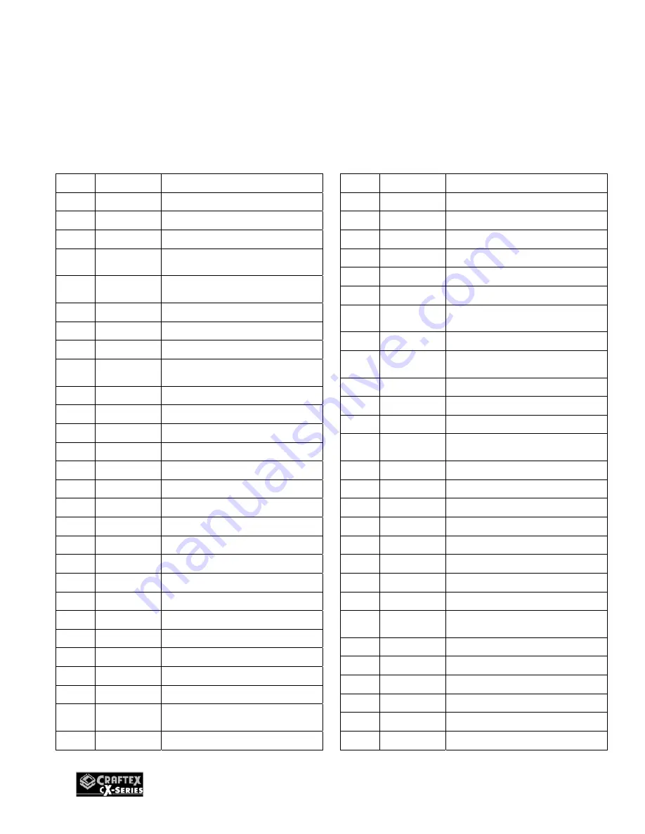
background image


20 


1 DJ-001 KNOB 
2 DJ-002 STUD 
3 DJ-003 BUSHING 
4 DJ-004 ECCENTRIC 

SHAFT 

5 GB80 

M6X16MM HEX SOC SET 
SCR. 

6 GB80 

M8X12MM HEX SOC SET 
SCR. 

7 DJ-005 FENCE 

CARRIAGE 

8 GB6170 

M6 

HEX 

NUT 

GB5782 

M6X25 HEX BOLT 

10  


FENCE CARRIAGE 
WARNING LABEL 

11 GB827  RIVET 
12 DJ-008  COLLAR 
13 DJ-012  SUPPORT 
14 DJ-014  WASHER 

12.7X38X5 

15 GB6170 M12 

HEX 

NUT 

16 

GB70 

M10X30MM SOC HD SCR 

17 DJ-013  WASHER 

10.4X30X3 

18 

GB70 

M5X16MM SOC HD SCR 

19 DJ-009  GIB 
20 DJ-010  ECCENTRIC 

STUD 

21 DJ-011  WASHER 

8.4X25X3 

22 GB6170 M8 

HEX 

NUT 

23 DJ-007  SHAFT 
24 

GB70 

M8X30 SOC HD SCR 

25 DJ-016  WASHER 

6.5X16X3 

26 DJ-015  POINTER 
27 GB97 

Φ

6MM FLAT WASHER 

28 GB65 

M6X16MM CHEESE HD 
SCR 

29 DJ-018  LOCK 

LEVER 

30 DJ-019  INDES 

PIN 

ASSEMBLY 

31 

GB879 

3X20MM ROLL PIN 

32 DJ-020  SPRING 
33 

GB5782 

M6X25 HEX BOLT 

34 GB6170 M6 

HEX 

NUT 

35 DJ-017  SWIVEL 
36 DJ-021  COLLAR 

37 GB80 

M8X12MM HEX SOC SET 
SCR. 

38 DJ-022  LOCK 

39 GB80 

M8X12MM HEX SOC SET 
SCR. 

40 DJ-023  CLAMP 
41 DJ-024  THREAD 

CLAMP 

42 DJ-025  TILT 

SCALE 

43 GB65 

M6X10MM CHEESE HD 
SCR 

44 GB97 

Φ

6MM FLAT WASHER 

45 DJ-026  BALL 

HANDLE 

46 DJ-027  STUD 
47 DJ-028  FENCE 
48 DJ-029  SCALE 
49 GB827  RIVET 
50 DJ-030B TABLE 

RH 

51 DJ-044B TABLE 

SHAFT 

52 DJ-032B 

RABBETING TABLE 
EXTENSION 

53 

GB70 

M6X20MM SOC HD SCR 

54 DJ-033B CHIP 

DEFLECTOR 

55 

GB70 

M6X12MM SOC HD SCR 

56 

GB70 

M8X80MM SOC HD SCR 

57 GB93  M8 

LOCK 

WASHER 

58 

DJ-034B 

BEARING BLOCK LH 

CX08HC JOINTER 

TABLE PARTS LIST 

REF#     PART#              DESCRIPTION 

REF#     PART#              DESCRIPTION 

Summary of Contents for CX08HC

Page 1: ...MODEL CX08HC 8 JOINTER WITH HELICAL CUTTERHEAD USER MANUAL Version 1 0 ...

Page 2: ......

Page 3: ...e immediate vicinity of your machine BE ALERT DO NOT use prescription or other drugs that may affect your ability or judgment to safely use your machine DISCONNECT the power source when changing drill bits hollow chisels router bits shaper heads blades knives or making other adjustments or repairs NEVER leave a tool unattended while it is in operation NEVER reach over the table when the tool is in...

Page 4: ... inspect your stock before feeding over the cutter head NEVER back your work piece into the spinning cutter head NEVER allow your hands to pass directly over the cutter head ALWAYS operate the jointer with a proper dust collection system ALWAYS make sure that the exposed cutter head behind the fence is guarded particularly when jointing near the leading edge such as in rabbetting NEVER LEAVE the j...

Page 5: ...V Belts Drive Max Depth of Cut 1 8 Max Width of Cut 8 Cutter Head Type Helical Cutter Head Speed 5 350 RPM Number of Carbide Inserts 40 Cuts per Minute 21 400 Table Size 8 Width 76 3 8 Length and Height from floor 32 5 8 Fence Size 1 1 4 Width 36 Length 5 Height 45 90 and 135 Stops Die Cast Metal Cutter Head Guard All Ball Bearing and Cast Iron Construction Shielded and Lubricated Ball Bearings Pr...

Page 6: ...Table Fence Fence Tilt Lock Fence Tilt Knob ON OFF Switch In feed Table Fence Lock Cutterhead Guard Outfeed Table Adjustment Lever Depth Scale Infeed Table Lock Mobile Base 4 Dust Hood Outfeed Table Adjustment Lever Outfeed Table Lock ...

Page 7: ...ion The machine is heavy and you should use a fork truck or get assistance to move the machine for safe moving method You should also clean the cutter head in feed and out feed tables and the fence before assembly and operation The hardware screws washers etc might be shipped in a plastic bag After the machine has been un packed check that all loose parts and hardware are present Figure 1 Minimum ...

Page 8: ... prong grounded receptacle as shown in figure 1 Do not remove the grounding prong to fit it into a 2 pronged outlet Figure 2 220 volts outlet for CX08HC It is strongly recommended not to use extension cords with your CX08HC Always try to position your machine close to the power source so that you do not need to use extension cords In case if you really find it necessary to use an extension cord ma...

Page 9: ...o move your machine again it is recommended that you use the in feed table as leverage when operating the foot pedal so that you do not hurt your back the machine is heavy so a strong rigid mobile base has been provided JOINTER BED Once the stand assembly of your jointer is on the ground now it is time to install the jointer bed to the stand Take the jointer bed out of the packaging and get the he...

Page 10: ... on the table and adjust the level of the table Once the table is completely leveled tighten all the cap screws shown in figure 4 Figure 6 Leveling the table FENCE To install the fence first you have to install the fence carriage to the table stand using washers and cap screws finger tighten See Figure 7 Figure 7 Installing the fence carriage Now take the fence out of the packaging and attach to t...

Page 11: ...tall the cutter head guard move the fence backward so that you have enough space Now insert the cutter head guard shaft and use the set screws to tight it See figure 10 Figure 10 Installing cutter head guard The guard is provided with spring so that when it gets pulled backward it spring back forward over the cutter head After you are done installing the guard test the guard by pulling it backward...

Page 12: ... through the hole located in the stand See figure 12 Figure 12 Installing the pedestal switch V BELT Your machine is provided with a V belt that goes around the motor pulley and the cutter head pulley To install the V belt loosen the motor bracket fasteners and slide the motor a little upward Now put the V belt around the motor pulley taking it around the cutter head pulley Then slide back the mot...

Page 13: ... make sure that the machine works properly and is ready for operation During the test run if there is any unusual noise coming from the machine or the machine vibrates immediately shut off the machine The problem might be because of the following 1 Belts slapping cover 2 V belts worn or loose 3 Pulley loose 4 Motor mounts loose or broken After you investigate and if you find that the problem with ...

Page 14: ...en connecting to a dust collector use a proper sized hose and make sure all the connections are sealed tightly SURFACE PLANING When surface planing on a jointer set the cutting depth to 1 32 and make sure the fence is set to 90 Place the concave face of the stock flat on the in feed table and run the jointer Push the stock over the cutter head with the help of push blocks as shown in figure 15 Fig...

Page 15: ...e in feed table See figure 17 Figure 17 Bevel cutting EDGE JOINTING Edge jointing is to make the edge of the stock flat and suitable for joinery or finishing To edge joint on the jointer set the cutting depth to 1 16 1 8 and make sure the fence is set to 90 degrees Place the concave face of the stock flat on the in feed table and run the jointer Use push blocks to push the stock over the cutter he...

Page 16: ...get dull after sometimes and need to be adjusted or replaced occasionally To adjust or replace the carbide inserts disconnect the machine from the power source and remove the cutter head guard to expose the cutter head with the carbide inserts Now take a hex key and loosen the screws on the carbide inserts that hold each carbide insert to the cutter head body See figure 19 Figure 19 Removing the c...

Page 17: ...ke a straight edge and place it on the out feed table so that it hangs over the cutter head Turn the eccentric bushings and lower the out feed table until the straight edge sits flat on the out feed table and just touches the cutter head Tighten the loosen screws See figure 21 Figure 21 Adjusting out feed table with the cutter head Now place the straightedge halfway across the in feed table and ha...

Page 18: ...r head body Now tighten the out feed table lock and the positive stop bolts and the jam nuts located at the back and front of the machine Set the knife height to the new out feed table height SETTING THE INFEED TABLE HEIGHT The positive stop bolts located at the back of the machine allows you to adjust the height of the in feed table The recommended setting for the minimum depth of cut is 1 32 and...

Page 19: ...19 CX08HC TABLE PARTS BREAKDOWN ...

Page 20: ...LAT WASHER 28 GB65 M6X16MM CHEESE HD SCR 29 DJ 018 LOCK LEVER 30 DJ 019 INDES PIN ASSEMBLY 31 GB879 3X20MM ROLL PIN 32 DJ 020 SPRING 33 GB5782 M6X25 HEX BOLT 34 GB6170 M6 HEX NUT 35 DJ 017 SWIVEL 36 DJ 021 COLLAR 37 GB80 M8X12MM HEX SOC SET SCR 38 DJ 022 LOCK 39 GB80 M8X12MM HEX SOC SET SCR 40 DJ 023 CLAMP 41 DJ 024 THREAD CLAMP 42 DJ 025 TILT SCALE 43 GB65 M6X10MM CHEESE HD SCR 44 GB97 Φ6MM FLAT ...

Page 21: ...10MM HEX SOC SET SCR 94 GB79 M6X10MM HEX HD SET SCR 95 DJ 054 LONG ADJUSTING SCR 96 DJ 060B SPRING 97 DJ 062 SPING PIN 98 DJ 055B CHIP BREAKER 99 GB97 M6 FLAT WASHER 100 GB5782 M6X12MM HEX HD SCR 101 DJ 011 FLAT WASHER 102 DJ 063B TABLE LOCK LEVER 103 DJ 056B ECCENTRIC BUSHING 104 DJ 057B TABLE SHAFT 105 GB80 M8X16MM HEX SOC HD SET SCR 106 DJ 058B TABLE SHAFT 107 DJ 059B POINTER 108 GB879 3X10MM R...

Page 22: ...22 CX08HC CABINET PARTS BREAKDOWN ...

Page 23: ...25 MOTOR PULLEY 226 GB78 M6X6MM HEX SOC SET SCR 227 GB1096 5X30 KEY 228 1 1 2HP MOTOR 229 GB70 M8X25MM SOC HD SCR 230 GB93 8MM LOCK WASHER 231 GB6170 M6 HEX NUT 232 GB97 6MM FLAT WASHER 233 M6X12MM PAN HD SCR 234 MAGNETIC SWITCH 235 GB896 9MM EXT RET RING 236 GB96 12MM FLAT WASHER 237 SHAFT 238 GB5780 M8X50 HEX BOLT 239 GB97 8MM FLAT WASHER 240 GB6184 M8 HEX NUT 241 GB6170 M10 HEX NUT 242 GB97 10M...

Page 24: ...er handy All returned merchandise will be subject to a minimum charge of 15 for re stocking and handling with the following qualifications Returns must be pre authorized by us in writing We do not accept collect shipments Items returned for warranty purposes must be insured and shipped pre paid to the nearest warehouse Returns must be accompanied with a copy of your original invoice as proof of pu...

Reviews: