


Pag. 52/53 MT-HC3TK15E1599NP-US 00
Procedure b)
The by-pass line is outside the acceptance field; the following message is seen on the
display panel:
BYPASS LINE VOLTAGE FAIL or SWBY OFF
1.
open all the switches on the device (SWIN, SWOUT, SWBY and the battery cabinet disconnectors/fuses).
The control panel will remain off.
2.
before closing switches SWMB and connecting the loads, ensure that both the frequency and voltage of
the supply line are sufficient to power the connected loads.
N.B.: After carrying out the operations indicated above, personnel must wait around ten minutes for the
capacitors to discharge before working on the inside of the CPS.
After the maintenance operations have finished, restart the CPS.
Close SWIN, SWBY, SWOUT on all the CPSs.
Close the disconnector or the fuses on the battery cabinets
Check that all the parallel-connected CPS are on.
Open all disconnector SWMB.
After a few seconds all the CPS will return to NORMAL OPERATION.
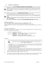
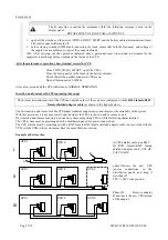
Insertion and removal with CPSs operating (hot swap)
The hot insertion and removal of the CPS can only take place if the system is configured with the
RJ45 female/RJ45
female
shielded adaptor cable
(as shown in the figures below).
The hot insertion and removal of the CPS makes technical support easier and improves the reliability of the system.
With this procedure it is not necessary to shut down all the CPSs in order to add or remove a unit.
Hot insertion and removal can only be done on systems comprising CPSs with the following characteristics:
The CPS system must be prearranged with a distribution panel (for power connections)
The CPS system must be prearranged with a RJ45 female/RJ45 female shielded adaptor cable (not provided with the
CPS)
.
All the CPSs in the system must have the same firmware version.
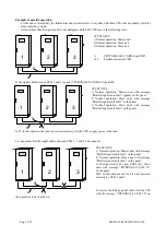
Example of hot insertion
A)CPS parallel cable type RJ45
B) RJ45 female/RJ45 female
shielded adaptor cable
CPS BY-
PASS CABLE
phase II Insert the new CPS
(power
connections
in
the
distribution panel) and keep it
switched off.
CPS 3: SW1 cont position.
Phase III
Remove adaptor
B and insert the new CPS instead
of the adaptor
.
UPS 3
A
UPS 1
A
UPS 2
A
I
II
III
B
UPS 1
UPS 2
UPS 3
UPS 1
UPS 2
Summary of Contents for C3T
Page 1: ...CPS C3T 15kVA three phase output User Manual ...
Page 2: ...Pag 52 53 MT HC3TK15E1599NP US 00 ...
Page 22: ...Pag 52 53 MT HC3TK15E1599NP US 00 This page is left blank intentionally ...
Page 32: ...Pag 52 53 MT HC3TK15E1599NP US 00 This page is left blank intentionally ...
Page 48: ...Pag 52 53 MT HC3TK15E1599NP US 00 This page is left blank intentionally ...


