


MT-HC3TKE301406NP-US 00 pag 39/53
J1
J2
J3
SW1
J1
J2
J3
SW1
LED
LED
5.4
Connection of signals
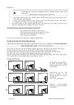
The signals of several parallel CPSs are connected in a closed loop configuration; if the loop is interrupted at any point,
either due to a fault or for maintenance, operation of the system is not compromised, and the system continues to
operate normally, as will be shown repeatedly below.
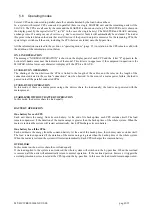
The various CPSs are connected through the “signals RJ45-flat-
adapter” parallel card, located in the lower part of the CPS (in
the area for signal and command connections as shown in the
section on SIGNALS and REMOTE COMMANDS).
- RJ45-flat-adapter signals parallel card.
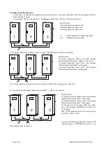
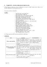
N.B.:
the CPSmay be provided with two versions of parallel
card that differ in the type of switch used (type 1 or type 2). The difference between the two switches is the position of
the control lever.
Type 1
type 2
LED side
connector side
J1 RJ45 type connector
J2 RJ45 type connector
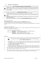
SW1
start position
connector side(type 1)
LED side (type 2)
Cont
position
LED side (type 1)
connector side (type 2)
LED
on
SW1 start position
off
SW1
Cont
position
Firmware update
All the parallel-connected CPSs must have the same firmware version. Press key 7 from the basic menu on
the display panel to display the firmware version installed.
For the expansion of an existing system, check that the system has the same firmware version as the new
CPS.
Summary of Contents for C3T
Page 1: ...CPS C3T 15kVA three phase output User Manual ...
Page 2: ...Pag 52 53 MT HC3TK15E1599NP US 00 ...
Page 22: ...Pag 52 53 MT HC3TK15E1599NP US 00 This page is left blank intentionally ...
Page 32: ...Pag 52 53 MT HC3TK15E1599NP US 00 This page is left blank intentionally ...
Page 48: ...Pag 52 53 MT HC3TK15E1599NP US 00 This page is left blank intentionally ...


