


30
INSTALLATION
INSTALLATION MANUAL
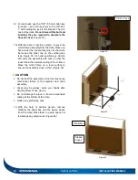
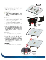
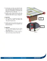
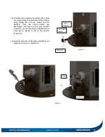
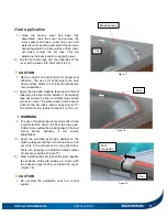
15) Fasten a short U-frame to each end of the front
frame cut-out and then install the entire
assembly between the front posts. Use four
hexagonal 5/16
″-18 x 2″ bolts, four 5/16″-18
nylon-insert lock nuts and eight
5/16″ washers
per side. Use 1/2″ (13 mm) socket wrench and
spanner. (Figure 59)
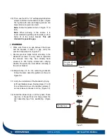
16) Verify whether the drive shafts fell off during
installation. If so, review the previous steps. If
not, tighten all U-frame bolts.
DANGER
Failure to verify the drive shafts installed could
result in the non-motor-side jacks elevating on
their own.
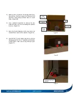
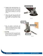
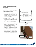
17) Once all the drive shafts have been installed,
the jack lock brackets located at the bottom of
the non-motor-side jacks can safely be
removed. Remove the Phillips M4 x 8 mm
screws. With the jack lock removed, screw back
in only the M4 x 8 mm screw. Keep the lock
bracket and the hardware for future use. (Figure
60). You can now remove the red paper tags
that are attached to the jacks.
WARNING
Failure to remove this part will break the lifting
mechanism.
Figure 59
Figure 60
M4 x 8 mm
screw
Jack lock
Summary of Contents for Evolution GHSC
Page 1: ...1 INSTALLATION MANUAL Revision 1 2017 05 29 Revision 2 2017 11 10...
Page 49: ...INSTALLATION MANUAL APPENDIX 49 APPENDIX...
Page 50: ...50 APPENDIX INSTALLATION MANUAL Wiring diagram North America 60 Hz 120 VAC Operator...
Page 51: ...INSTALLATION MANUAL APPENDIX 51 Wiring diagram Europe 50 Hz 220 VAC Operator...
Page 53: ...INSTALLATION MANUAL INSTALLATION CHECKLIST Customer copy 53...
Page 56: ...56 INSTALLATION MANUAL...


