4
EN
GL
IS
H
10
1
10
2
3
4
5
6
7
9
10
11
12
8
13
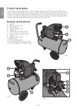
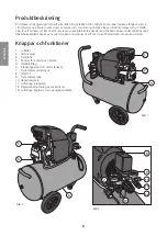
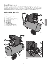
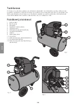
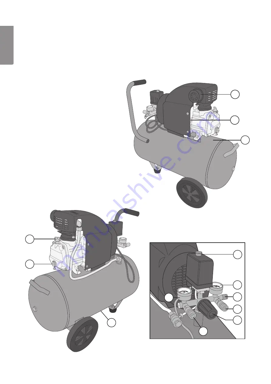
Fig. 1
Fig. 2
Fig. 3
Product description
The compressor increases the pressure of the air which is pumped into the pressure vessel. When the air
pressure in the vessel reaches max, a pressure switch switches off the motor driving the compressor. At the
same moment, the air in the compressor is released. This occurs to reduce the pressure in the compressor
so that it can restart when the pressure drops to below the minimum pressure. A safety valve releases the air
in the pressure vessel if the pressure switch should fail to turn the motor off.
Buttons and functions
1. Air filter
2. Motor overload cut-out
3. Pressure vessel
4. Oil level display window
5. Oil filler cap
6. Drain tap (under pressure vessel)
7. Pressure gauge – working pressure
8. ON/OFF
9. Pressure gauge - vessel
10. Safety valve
11. Air outlet (unregulated)
12. Pressure regulator (working pressure)
13. Air outlet (regulated, controlled by valve)
Summary of Contents for ZB-0.12/8-50FL
Page 2: ...2...

