background image


User Manual 


99 


6.


Webviewer 

This chapter describes webviewer for monitoring videos through a PC in remote mode.   

How to monitor with webviewer. 


Table 6-1 System Requirement for Webviewer 

Item 

Recommended 

Minimum 

OS 

Microsoft

  Windows

  10 x86(64bit) 

(Home Premium, Professional, Ultimate) 

Microsoft

  Windows

  8(pro, Enterprise) 

Microsoft

  Windows

  XP Home SP3 

CPU 

Intel CoreTM i5-2550 3.30GHz or higher 

Intel CoreTM 2 Duo E7200 2.53GHz or 

higher 

RAM 

2GB or higher 

1.5GB or higher 

VGA 

ATI RadeonTM HD 3650 or NVIDIA 

GeForce 8400GS or higher (1280x1024, 

32bpp or Higher), Multi Monitor 

ATI RadeonTM HD 2400 or NVIDIA GeForce 

FX5500 or higher (1024x768, 24bpp or 

higher) 

HDD 

Over 6GB 

Over 1GB 

LAN 

Gigabit Ethernet   

10/100 Mbps Ethernet 


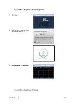
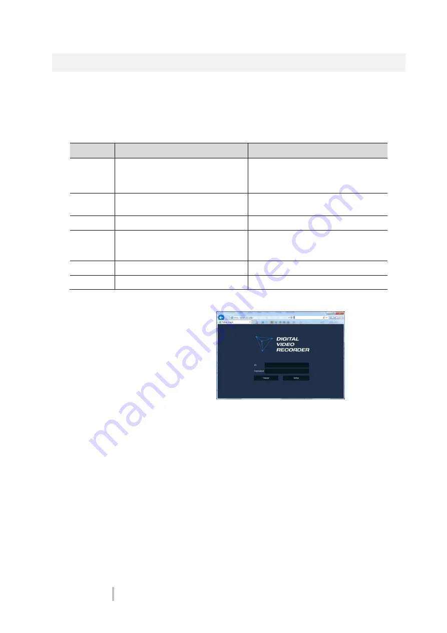
Enter IP address of a recorder in   


Internet browser.   


2  Enter ID and Password, and then click the 

button. 


Viewer: playing NVR Live images 


Setup: setting menu in similar ways 
with NVR connected monitor. 


For using Viewer, users need to download Java. The way to download is shown as follows:     

Summary of Contents for COSCR04CH20-2TB

Page 1: ...User Manual 4 8 16 Channel DVR Digital Video Recorder Please read this manual thoroughly before use and keep it handy for future reference ...

Page 2: ...e user to the presence of dangerous voltage within the products enclosure that may be ofenoughmagnitudetoconstituteariskofelectricshock to persons The exclamation point within an equilateral triangle is intended to alert the user to the presence of important operating and maintenance servicing instructions in the literature accompanying theproduct CAUTION RISK OF ELECTRIC SHOCK DO NOT OPEN WARNING...

Page 3: ...te radiofrequency energy and if not installed and used in accordance with the instruction manual may cause harmful interference to radio communications Operation of this equipment in a residential area is likely to cause harmful interference in which case the user will be required to correct the interferenceat his own expense This device complies with Part 15 of the FCC Rules Operation is subject ...

Page 4: ...rom the apparatus 11 Only use attachments accessories specified by the manufacturer 12 Use only with the cart stand tripod bracket or table specified by the manufacturer or sold with the apparatus When a cart is used use caution when moving the cart apparatus combination to avoid injury from tip over 13 Unplug this apparatus during lightning storms or when unused for long periods of time 14 Refer ...

Page 5: ...3 Network 12 2 4 4 Time Date 13 2 4 5 Record 13 2 4 6 Easy Installation Wizard 14 3 Live Screen Configuration 15 3 1 Icons in Live screen 16 3 2 Live Launcher menu 17 3 2 1 Backup 18 3 3 Quick menu 20 3 3 1 PTZ Control 22 3 3 2 Camera Registration 23 3 3 3 Status System log 25 3 3 4 Status Event 26 3 3 5 Status Record 27 3 3 6 Status Disk 28 4 Setup menu 29 4 1 General buttons in Setup menu 31 4 2...

Page 6: ...Schedule 60 4 5 2 Main Stream 64 4 5 3 Second Stream 68 4 5 4 Panic 71 4 6 EVENT 72 4 6 1 System Disk 72 4 6 2 Alarm In 74 4 6 3 Motion 77 4 6 4 Video Loss 79 4 6 5 Notification 80 4 7 NETWORK 82 4 7 1 Basic WAN Port 82 4 7 2 Basic IP Filter 83 4 7 3 DVRNS DDNS 84 4 7 4 E Mail 86 4 7 5 FTP 87 4 7 6 P2P 88 4 7 7 Notification Server 89 5 Search Playback 92 5 1 Search 92 5 2 Playback 96 6 Webviewer 9...

Page 7: ...ng a network The device features include the following Support H 264 and H 265 compression Convenient UI from user s viewpoint Composite input port for 4 8 16 channels Providing AHD TVI 960H and D1 4K 3840x2160 HDMI output 4Mega pixel screen recording audio recording and playing HDD information and status presentation HDD overwriting USB Data Back up Simultaneous recoding and playing of 4 8 16 cha...

Page 8: ...racket 8 16ch only 5 Program CD 10 Bracket fixing screw 8 16ch only 1 2 DVR Description Each part is listed in the below Figure 1 1 Name and Connection of each front section Table 1 2 Name and Function of each front section No Name Function 1 Power status LED Pointing out device on off 2 Recording status LED Pointing out recording in process 3 Network LED With a network viewer pointing out network...

Page 9: ...of 4ch 8ch and 16ch DVR No Name Function 1 Audio In Camera audio input port 2 Video In Camera video input port 3 CVBS CVBS output port 4 Audio Out Audio output port 5 VGA VGA output port 6 HDMI HDMI output port 7 LAN Network connector 8 USB USB port is connected for USB mouse or firmware upgrade and data back up 9 Alarm In Out Alarm connector 10 RS485 RS 485 communication connector ...

Page 10: ...User Manual 6 No Name Function 11 DC12V Connector with power supply 12 Power Switch Power On Off ...

Page 11: ...R When installing a device connect rear of the device with each port on the basis of below connection map Figure 2 1 Connection map The device starts first like below sequences 1 Installing HDD 2 Connecting with an exterior device 3 Starting a system 4 Setting a quick setup ...

Page 12: ...to connect each port to rear section of the unit 1 Place the unit in a stable flat surface 2 Make a room between front rear sides of the device not to break connectors Warning Do NOT install the device too close to the wall Protrusive connects rear the unit may be forcedly curved or pressed which cause fires electric shocks or injury 3 Check to switch off and unplug the unit Warning Make sure to w...

Page 13: ...ect a network port 8 Connect an alarm and RS485 devices 9 Connect USB port in front or rear section of the unit with a mouse or other USB devices 10 Connect DC12V adapter 11 Turn on the switch after completion Attention Before connection match socket with adapter pins ...

Page 14: ... new HDD might take more initialize time 2 With buzzer sounds the start screen is presented 3 In Log in screen enter the ID Password and press OK Note Default ID Password is admin admin Click to see the MAC address If lost password inform the MAC address to supplier to create temporary password Attention Please change password after login due to security ...

Page 15: ... 4 Time Date 5 Record 2 4 1 Account How to set Account of Easy Installation 1 Click the keyboard icon to set ID and Password users want 2 With keyboard UI set the ID and Password and press OK 3 Press the Save button to save newly set ID and Password 4 Press Next button to end Account setting and move the next setting phase ...

Page 16: ...cting the device ID In case of simultaneous use of equipment set ID with difference HDMI VGA Set resolution of a monitor connected to the device 2 Press Save button to save set value 3 Press Next to end System setting and move the next setting phase 2 4 3 Network How to set the network of Easy Installation 1 Set each item in Network setting screen WAN Port Select whether to use static IP or dynami...

Page 17: ... Daylight saving time select DST Time Zone Select time zone for the system being installed DST Start End For applying Daylight saving time set the application period 2 Press Save button to save set value 3 Press Next to end Time Date setting and move the next setting phase 2 4 5 Record How to set the record of Easy Installation 1 Set each item in Record setting screen Select desired recording peri...

Page 18: ...e rate and resolution 2 Press Save button to save set value 3 Press Next to end Network setting and move the next setting phase 2 4 6 Easy Installation Wizard Select to run Easy Installation every time when the system start 4 Press Save button to save set value and end Easy Installation ...

Page 19: ...ive video of connected cameras 3 Launcher menu Launcher menu is located in the corner of below screen See 3 2 Live Launcher to display detailed information about the launcher menu 4 Quick menu Clicking the right button of a mouse displays Quick menu See 3 3 Quick menu to display detailed information about the quick menu 5 Add to CH It is manual registration menu when the mouse pointer is placed in...

Page 20: ...yellow one Figure 3 2 Live screen icon Table 3 2 Live screen icon and its description No Icon Description 1 CH1 CAM1 Channel numbers and camera titles 2 A camera with PTZ function 3 PTZ control function in process 4 Recording in alarm event mode 5 Recording in motion event mode 6 Recording in panic recording mode 7 Recording in consecutive recording mode 8 Video loss icon 9 Mic on off 10 Speaker o...

Page 21: ...in order set toggle 6 Selecting partition mode to mark in live screen single screen 4 9 and 16 partition 7 Stopping or replaying selected live screen images toggle 8 Audio on or mute chosen live screen toggle 9 Save the bookmark 10 Make a backup video of users want See 3 2 1 Backup to display detailed information about back up 11 Searching recording data time event thumbnail smart search and text ...

Page 22: ... bookmark list 4 End Setting back up ending time Bookmark bookmark list 5 Time Overlap Selecting time if there are two recorded data in the same time 6 Backup Mask User can mask selected area It works H4V format only 7 Device Selecting the device to save back up files 8 Reload Opening the device information 9 Folder Name Entering a folder name to save back up files 10 AVI H4V Selecting a file form...

Page 23: ...Select Backup Mask and click SET button to open the Privacy Mask pop up window Figure 3 5 Backup Mask Table 3 5 Backup Mask Item and Description No Item Description 1 Select CH Select the channel to set the privacy zone 2 Privacy Mask Enable Select whether to use the Privacy Mask 3 Mask Zone Apply all or only the selected mask 4 New Mask Create a new privacy zone Up to 4 masks can be created 5 Del...

Page 24: ...Monitor Set the output mode of a spot monitor Auto Full and 2x2 Auto Full and 3x3 Auto Full and 4x4 8 Playback Playing selected live screen images from 30 sec ago 1 min ago 5 min ago 10 min ago 30 min ago 1 hour ago go to first and Go to last 9 Search Searching recording data time event thumbnail text and VCA See 5 1 Search to display detailed information about search 10 Backup Backup video users ...

Page 25: ...User Manual 21 No Item Description 15 Shutdown Shuts down or restarts the device shutdown ...

Page 26: ... live screen Figure 3 7 Quick menu PTZ Control Table 3 7 Quick menu PTZ Control Item and Description No Item Description 1 Moving images with direction buttons 2 Moving images with PTZ ball 3 AF Adjusting screen focus automatically 4 Zoom Out Zoom function of PTZ camera 5 Zoom In 6 IRIS OFF Adjusting iris in the camera 7 IRIS On 8 Focus Far Manual focus adjustment 9 Focus Near 10 Open camera menu ...

Page 27: ...rol Quick menu Table 3 8 PTZ Control Item and Description in Quick menu No Item Description 1 Preset Tour Scan Pattern Run PTZ functions 2 Exit Transforming to live screen menu in PTZ Control menu 3 3 2 Camera Registration Users can register the IP cameras if user select Analog IP mode Figure 3 9 Camera Registration ...

Page 28: ...tatus 8 Priority If IP camera has both IP address and Zero Conf IP address only one address will be searched according to the selected priority 9 Add Manually Select channel and click to open manual add window Add Manually Click to open Camera Registration Or move the mouse point at the middle of channel on the live screen and click the Figure 3 10 Camera Registration manual add Table 3 10 Camera ...

Page 29: ...og tap in Status screen Figure 3 11 Status System log in Quick menu Table 3 11 Status of Quick menu System log Item and Description No Item Description 1 Start Setting starting time of system log to search 2 End Setting ending time of system log to search 3 Log Type Selecting log types Network Record Setup Disk Backup and System 4 Select All Unselect All Selecting or clearing all log types toggle ...

Page 30: ...tap in Status screen Figure 3 12 Status Event in Quick menu Table 3 12 Status Event Item and Description in Quick menu No Item Description 1 Temporary fixing or releasing an event list toggle 2 Refresh Deleting the event list 3 Event list Displaying the event list 4 Cancel Completing the status screen ...

Page 31: ...Record tap in Status screen Figure 3 13 Status Record in Quick menu Table 3 13 Status Record Item and Description in Quick menu No Item Description 1 Record time Marking recorded period 2 Record list Displaying the record setting status 3 Cancel Completing the status screen ...

Page 32: ...tap in Status screen Figure 3 14 Status Disk in Quick menu Table 3 14 Status Disk Item and Description in Quick menu No Item Description 1 Disk Info Display disk temperature and S M A R T information 2 Rec Info Display recording period 3 Cancel Completing the status screen ...

Page 33: ...available to click Setup in Quick menu by clicking the right button of the mouse Table 4 1 Setup menu Item and Description No Item Description 1 SYSTEM Setting the system environment 2 CAMERA Setting the camera 3 DEVICE Setting the non camera device connected with the DVR 4 RECORD Setting the recording parameters 5 EVENT Setting each event 6 NETWORK Setting the network environment ...

Page 34: ...ser Configuration Export Import Factory Default CAMERA Basic Basic Audio In Out Advanced Scan Mode Advanced DEVICE Display Display Spot OSD Sequence Disk Setup iSCSI PTZ PTZ Serial Device Serial Device TEXT TEXT RECORD Schedule Schedule Quick Stream Mainstream Second Stream Panic EVENT System Disk System Disk Alarm In Setup Schedule Motion Setup Schedule ...

Page 35: ...tion Server Notification Server Notification Message 4 1 General buttons in Setup menu This section depicts General buttons in Setup menu Figure 4 2 General buttons in Setup menu Table 4 3 Item and Description of General buttons in Setup menu No Item Description 1 Default Reverse changed setting value to default in factory 2 Save Save the set content 3 Cancel Cancel the set value ...

Page 36: ...sic items in the System Figure 4 3 SYSTEM System System Table 4 4 SYSTEM System System Item and Description No Name Function 1 Language Set the system language 2 Device Name Enter the device name Only English is possible 3 Video Type Select image standard types NTSC PAL 4 Keyboard ID Select keyboard ID 1 255 5 Remote Control ID Select wireless remote control ID 1 99 6 System start Select Easy Inst...

Page 37: ...on Displaying the present tool version 2 Device Connect USB memory that has files to upgrade to the USB port select files to upgrade Note If firmware version in the USB drive is lower than present system version system does not display the firmware in the USB drive To upgrade through network recorder must have HDD Warning If change video type system will reboot and all setup go to factory default ...

Page 38: ...whether to use summertime Time change Save changed time 2 DST Start Set the starting date of summertime 3 DST End Set the ending date of summertime 4 Display Format Select the format to present date and time 5 Time Zone Select time zone 6 Network Time Sync For using a specific network time server click the Use checkbox and enter the server address Sync Interval Select synchronization period 1 7 ho...

Page 39: ...of the system Figure 4 6 SYSTEM Time Date Holiday Table 4 7 SYSTEM Time Date Holiday Item and Description No Name Function 1 Year Select years to set holidays 2 Delete selected holidays 3 Add Holiday Add holidays 4 List Display added holiday lists ...

Page 40: ...oliday Table 4 8 SYSTEM Time Date Holiday Add Holiday Item and Description No Name Function 1 Name Enter the holiday name 2 Date Display chosen date 3 Type Select the holiday types e g Selecting Relative and 1 first and Sun which designates annual January of the 1st Sunday as a holiday 4 Calendar Select the holiday to add ...

Page 41: ... 4 User List Display user lists across groups 5 Live view restricted access Do not display live video if log it out 6 ADUP Archive Dual User Permission Two users should access to search playback and back up 7 Auto Login Click clear the automatic login checkbox 8 Auto Logout Select automatic logout time Null 1 min 2 min 3 min 4 min 5 min 6 min 7 min 8 min 9 min 10 min and 30 min 9 Password Change C...

Page 42: ...me 2 PERMISSION Select items to permit access 3 Select channels to permit access Press Add User button then Add User screen displays Figure 4 10 SYSTEM Account User Add User Table 4 11 SYSTEM Account User Add User Item and Description No Name Function 1 Name Enter the username 2 ID Enter the user ID 3 Password Enter the password 4 Confirm Password Confirm the password 5 Group Select to the group t...

Page 43: ... connector with USB USB Displays the USB device connected Refresh button Re recognize the device 2 Import Apply information saved in USB to the device Import Config with network setup The network setting information is brought from the setting information Import button The file in USB is brought to the designated device 3 Export Save the set information in the USB Export Config with network setup ...

Page 44: ...2 SYSTEM Config Factory Default Table 4 13 SYSTEM Config Factory Default Item and Description No Name Function 1 Select All Unselect All Select deselect all items to be defaulted 2 Default Item Select deselect related items to be defaulted 3 Default button Default the system to the basics ...

Page 45: ...nnels Figure 4 13 CAMERA Basic Basic Table 4 14 CAMERA Basic Basic Item and Description No Name Function 1 CH Display the channel name 2 Title Enter the camera name of relevant channels 3 Covert Select images to be shown in the Live screen by channels and whether to mark a status message or not Off Video Only Video State All 4 Copy Covert Setup In Convert set items can be duplicated to other chann...

Page 46: ... displays Figure 4 14 CAMERA Basic Basic Copy Covert Setup Table 4 15 CAMERA Basic Basic Copy Covert Setup Item and Description No Name Function 1 From Select a channel converted setting 2 To Select a channel to be copied 3 Select All Unselect All Select deselect all channels ...

Page 47: ...MERA Basic Audio In Out Table 4 16 CAMERA Basic Audio In Out Item and Description No Name Function 1 No Display channels of audio 2 Use Select deselect whether to use audio 3 Assign Displays the channels to which audio is assigned 4 Record Select deselect whether to save audio when recording ...

Page 48: ...nced Scan Mode Table 4 17 CAMERA Advanced Scan Mode Item and Description No Name Function 1 CH Display channels 2 Scan Mode Automatically detects the camera input type or fixes the input video format to the selected type Auto AHD TVI 3 Copy Scan Mode Copies the currently set scan mode settings to another channels ...

Page 49: ...og Camera Table 4 18 CAMERA Advanced Analog Camera Item and Description No Name Function 1 CH Display channels 2 Video Set brightness contrast and color of the camera 3 Privacy Mask Set the privacy field display field numbers set in parenthesis at most 4 setting available ...

Page 50: ...select whether to use privacy field 3 New Mask Select privacy field again 4 Delete Mask Delete selected privacy field How to set Privacy Mask Users might set 4 Privacy Masks and the way to set Privacy Mask is as follows 1 Press New Mask button Mask Zone is automatically set as Mask1 2 Drag the area you want in the screen with a mouse Revision Select Mask No in Mask Zone and drag the area you want ...

Page 51: ... Description No Name Function 1 Camera Registration Opens a pop up menu for IP camera registration 2 CH Display channels 3 Video Set brightness contrast and color of the camera 4 Stream Setup camera stream such as Resolution Framerate Bitrate and etc Note This menu will be appeared when Analog IP cam mode is selected ...

Page 52: ... Display Display Set the display device Figure 4 20 DEVICE Display Display Table 4 21 DEVICE Display Display Item and Description No Name Function 1 HDMI VGA Select the resolution of the display device 1024x768 1280x720 1920x1080 3840x2160 2 Event Popup Set duration of event popup 3 Monitor Relay Switch Send alarm out when screen layout changed ...

Page 53: ...Name Function 1 Sequence Set the channel and dwell time 5 10 20 30sec when the Auto mode of Spot Monitor is selected 2 Event Popup Sets the hold time of the full screen image of the channel where the event occurred Off 5 10 20 30sec Continuous If multiple channels have an event at the same time the event channel is shown as a spilt screen Display OSD ...

Page 54: ...Table 4 23 DEVICE Display OSD Item and Description No Name Function 1 Camera Name Select the way to display camera in live screen Off CH Title CH 2 Live Bar Select the way to display the live bar Always On Auto Hide 3 Display Icon Select deselect icons to display in the live screen ...

Page 55: ...d in the below table All Full and Quad 3 Sequence List Display the sequence list based on division selected value 4 Add Sequence Add items to be included in the play sequence 5 No Automatically controvert screens in number order 6 Division Displays as full 2X2 Quad 7 CH List Set automatic conversion CHs In case of choosing CH3 in No 1 CH3 is shown in advance 8 Dwell Time Set the remaining time for...

Page 56: ...creen Figure 4 24 DEVICE Display Sequence Add Sequence Table 4 25 DEVICE Display Sequence Add Sequence Item and Description No Name Function 1 Dwell Time Select time to play 3 sec 5 sec 10 sec 15 sec and 30 sec 2 Division Select the partition screen to play Full ...

Page 57: ...Status disk status 3 Rec Info Display saved disk information in disc list Start Recording Time starting time for saving information in the disk End Recording Time ending time to stop saving information in the disk Status disk status 4 S M A R T Display S M A R T information in disc list Model disk model name Temp disk temperature Alive Time running time after turning on the disk S M A R T a presen...

Page 58: ...o delete saved data automatically 1 365 days Disk iSCSI The way to set the iSCSI Figure 4 26 DEVICE Disk iSCSI Table 4 27 DEVICE Disk iSCSI Item and Description No Name Function 1 Register Opens a pop up menu for iSCSI registration 2 Delete Delete registered iSCSI storage 3 Detail Display selected iSCSI IP address and port number Note Recorder support Max 6 volumes Target Node Each volume supports...

Page 59: ...Table 4 28 DEVICE Disk iSCSI Register Item and Description No Name Function 1 Target Address Target Port HTTP Port Input IP address and port for iSCSI 2 Discover Click to search iSCSI storage 3 Username Enter the username 4 Password Enter the password 5 Add Click to register the discovered iSCSI storage ...

Page 60: ...py PTZ Setup Apply setting history to all or selected channels in the same way 2 CH Display channels 3 ID Select camera ID connected to relevant channels 1 255 4 Protocol Select protocol of camera connected to relevant channels 5 Speed Select pan tilt of camera connected to relevant channels 1 5 Note For more information about camera ID protocol information and details see Instruction of relevant ...

Page 61: ... camera USB device with the unit Figure 4 29 DEVICE Serial Device Serial Device Table 4 30 DEVICE Serial Device Serial Device Item and Description No Name Function 1 USB to Serial Set communication transmission value of USB device 2 RS 485 Set communication transmission value of RS 485 connector ...

Page 62: ...lect whether to use text function 2 CH Select camera channels to connect with the text input device 3 Protocol Select protocol to correspond with the text input device 4 ID Port Select ID and port no to correspond with the text input device 5 Input Char Set Select a character format of the text input device 6 Copy TEXT Setup As for connecting multiple units duplicate set value to others ...

Page 63: ...re 4 31 DEVICE TEXT TEXT Copy TEXT Setup Table 4 32 DEVICE TEXT TEXT Copy TEXT Setup Item and Description No Name Function 1 From Select channels set 2 To Select the device to be copied 3 Select All Unselect All Select deselect all channels 4 Copy Item Select deselect items to be copied ...

Page 64: ...ure 4 32 RECORD Schedule Schedule Table 4 33 RECORD Schedule Schedule Item and Description No Name Function 1 CH Select channels to set schedules 2 Schedule Type Selection Select the types of schedules 3 Schedule Table Display the schedule users set 4 Drag Field Display the area dragged with a mouse 5 Copy Schedule Setup Copy set recording schedule to other channels ...

Page 65: ...cording C A Record on event recording mode when alarm occurs during consecutive mode recording M A Record on event recording mode when only alarm and motion sensitive event occur C M A Record on event recording mode when only alarm and motion sensitive event occur during consecutive mode recording The way to schedule recording across channels 1 Select channels to schedule 2 Select items in schedul...

Page 66: ...chedule Setup screen displays 8 Select channels to be copied 9 Select channels to apply copied content 10 Copy the schedule by pressing Apply 11 Press Save to save the schedule Schedule Quick Figure 4 33 RECORD Schedule Quick ...

Page 67: ...eriod 2 Recording Hours per Day Select recording hours per day 3 HDD Size It is automatically displayed 4 Stream Priority Select Framerate or Resolution 5 Recording mode Select recording mode as Continuous or Event 6 Audio Enable if audio is recorded 7 Calculation User can see recommended resolution and frame rate to meet recording period ...

Page 68: ...nd 960H 3 Continuous Select recording FPS and image quality in consecutive recording Frame Rate recording FPS selection 1 30 Quality recording image quality selection Level 1 8 4 Event Select recording FPS and image quality in event recording Frame Rate recording FPS selection 1 30 Quality recording image quality selection Level 1 8 5 Pre Alarm Start recording before set time if event occurs null ...

Page 69: ...Table 4 37 RECORD Stream Main Stream Copy Stream Setup Item and Description No Name Function 1 From Select the channel set 2 To Select the device to be copied 3 Select All Unselect All Select deselect all channels 4 Copy Item Select deselect items to be copied Main Stream IP Camera Figure 4 36 RECORD Main Stream IP Camera ...

Page 70: ... Continuous Select recording stream in case of Continuous mode 4 Event Select recording stream in case of Event mode 5 Pre Alarm Start recording before set time if event occurs null 1 sec 2 sec 3 sec 4 sec and 5 sec 6 Post Alarm Recording after set time until event ends null 5 sec 10 sec 30 sec 1 min 5 min and 10 min Note This menu will be appeared when Analog IP cam mode is selected ...

Page 71: ...c Type Item and Description No Name Function 1 CH Display channels 2 Main Stream Select the main stream codec H 264 H 265 3 Sub Stream Select the sub stream codec H 264 H 265 4 Copy Codec Setup Copy current selected codec to another channel Clicking Copy Codec Setup opens Copy Stream Setup Figure 4 38 RECORD Main Stream Codec Type Copy Codec Setup ...

Page 72: ...t to be copied 4 5 3 Second Stream Second Stream Analog Camera To set the image quality and resolution of Second Stream Figure 4 39 RECORD Stream Second Stream Table 4 41 RECORD Stream Second Stream Item and Description No Name Function 1 CH Display channels 2 Resolution Set the resolution of video clips 640X480 3 Frame Rate Select recording FPS 1 30 4 Quality Select image quality Level 1 8 5 Pre ...

Page 73: ...User Manual 69 No Name Function 7 Copy Stream Setup Copy main recording image set value to other channels For more information about set value copy see section 4 5 2 Stream Main Stream in Main Stream ...

Page 74: ... Camera Item and Description No Name Function 1 CH Display channels 2 Resolution Framerate Bitrate Show camera main stream setup status 3 Pre Alarm Start recording before set time if event occurs 4 Post Alarm Recording after set time until event ends Note This menu will be appeared when Analog IP cam mode is selected ...

Page 75: ...o Name Function 1 Panic Record Select deselect to use immediate recording function 2 CH Display channels 3 Resolution Set the resolution of video clips 4MP 1080P 720P 960H 4 Frame rate Select recording FPS 1 30 5 Quality Select image quality Level 1 8 6 Dwell Time Select recording duration No limits 10 sec 30 sec 1 min 5 min 10 min and 30 min ...

Page 76: ...2 Event System Disk System Table 4 44 Event System Disk System Item and Description No Name Function 1 System Restart Select deselect whether to use system restart event 2 Notification Select deselect whether to use mailing or mobile push in case of event 3 User Login Select deselect whether to use user login event 4 Record Transaction Select deselect whether to use record transaction event ...

Page 77: ...ent 2 Beep Select deselect whether to use buzzer sound in case of event 3 Alarm out Select to end alarm time null Relay1 Keep 5 sec 10 sec 20 sec 30 sec 1 min 10 min 30 min and 1 hour 4 Notification Select deselect whether to use mailing or mobile push in case of event 5 Disk Full Set disk capacity for disk full event Off 50 60 70 80 90 and 100 6 S M A R T Fault Select deselect whether to use S M ...

Page 78: ...t sensor types N O N C 4 Assign Select camera channels to designate a sensor CH 1 4 8 16 immediate recording 5 Beep Select use time of buzzer sound null 5 sec 10 sec 20 sec 30 sec 1 min 10 min 30 min and 1 hour 6 Alarm Set alarm output 7 Group Rec Select the camera to record simultaneously 8 Noti Set email notices 9 Preset Set preset of PTZ camera 10 Copy to Alarm Setup Copy alarm set value to oth...

Page 79: ...utput checkbox Dwell Time Selecting alarm duration Keep 5 sec 10 sec 20 sec 30 sec 1 min 10 min 30 min and 1 hour 2 Group Recording Select deselect whether to use Group Recording 3 Simultaneous recording camera channel screen opens 4 Monitor Popup Select deselect whether to use Monitor Popup 5 Channel selection screen opens 6 Remote Notification Select deselect whether to use remote mailing 7 Pres...

Page 80: ...the schedule 2 Schedule Type Selection Select the types of schedules 3 Schedule Table Display the schedule users set 4 Drag Field Display the area dragged with a mouse 5 Copy Alarm Schedule Copy the schedule on alarm set to other sensors For more information about set value copy see section 4 5 2 Stream Main Stream in Main Stream Note For more details about scheduling recording time when alarm occ...

Page 81: ...he channel 3 Area Display the motion area 4 Sens Select the sense level of the motion sensor Level 1 10 5 Beep Select use time of buzzer null 5 sec 10 sec 20 sec 30 sec 1 min 10 min 30 min and 1 hour 6 Alarm Set alarm output 7 Group Rec Select the camera to record simultaneously 8 Noti Set email notices 9 Preset Set preset of PTZ camera 10 Copy to Motion Setup Copy motion set value to other channe...

Page 82: ...eld Display the area dragged with a mouse 5 Copy to Motion Schedule Copy the motion detection schedule to other channels For more information about set value copy see section 4 5 2 Stream Main Stream in Main Stream Note For more information how to schedule record time when the motion sensor detects across channels see section 4 5 1 Schedule Note Placing your mouse on Alarm Group Rec Noti Preset an...

Page 83: ... min and 1 hour 4 Alarm Set alarm output 5 Group Rec Select the camera to record simultaneously 6 Noti Set email notices 7 Preset Set preset of PTZ camera 8 Copy Video Loss Setup Copy the Video Loss set value to other channels For more information about set value copy see section 4 5 2 Stream Main Stream in Main Stream Note Placing your mouse on Alarm Group Rec Noti Preset and clicking editing ico...

Page 84: ...iption No Name Function 1 Periodic Notification Select deselect whether to use periodical alarms 2 Summary Send the save or event information Record sending the save information Event sending the event information 3 Interval Set the alarm interval 5 min 10 min 30 min and 1 hour 2 hour 6 hour 8 hour 12 hour and 24 hour 4 Select CH Select channels users want 5 Select All Unselect All Select deselect...

Page 85: ...53 EVENT Notification Schedule Item and Description No Name Function 1 Schedule Type Selection Select the types of schedules 2 Schedule Table Display the schedule users set 3 Drag Field Display the area dragged with a mouse Note For more information how to schedule record time when the alarm is detected see section 4 5 1 Schedule ...

Page 86: ...to use DHCP Dynamic 3 MAC Address Display the MAC Address 4 DNS Select manual and enter DNS otherwise choose automatic function 5 Port TCP Enter TCP port 6 Encryption Select the Encryption box for video data by using TCP port Select to encrypt for video data through TCP port 7 Port HTTP HTTPS Enter HTTP HTTPS port 8 Redirect to HTTPS Select to allow HTTPS to connect by request 9 Bandwidth Limit Se...

Page 87: ... Filter Table 4 54 NETWORK Basic IP Filter Item and Description No Name Function 1 Mode Select None to disable Select Access to access IP address range Select Deny to restrict IP address range 2 Range Start Enter the Start IP address to Access or to Deny 3 Range End Enter the End IP address to Access or to Deny ...

Page 88: ...and Description No Name Function 1 DVRNS Register DVRNS account ID Enter DVRNS ID default MAC address of the unit Password Enter DVRNS password Register Register DVRNS account 2 Dashboard Add delete Dashboard account Account Select the types of account Existing Account or New Account ID Enter Dashboard ID Password Enter Dashboard password Add Device Add Dashboard account Delete Device Delete Dashb...

Page 89: ... to access in networking Figure 4 54 NETWORK DVRNS DDNS DDNS Table 4 56 NETWORK DVRNS DDNS DDNS Item and Description No Name Function 1 DDNS Site Select DDNS site 2 Host Name Enter the host name 3 User Name Enter the user name 4 User Password Enter the user password ...

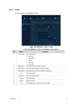
Page 90: ...server gmail com hotmail com aol com naver com daum com 2 Address Port Enter server address and port number 3 Image Attach Select deselect whether to attach JPG image 4 Authentication Select deselect using authentication and password 5 ID Enter the email ID 6 Password Enter the email password 7 Sender Write the sender 8 Receiver Write the receiver 9 Test Verify whether the email server is set norm...

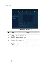
Page 91: ...er Select whether to use FTP 2 Address URL Port Enter server address and port 3 ID Password Enter ID Password of server 4 Upload Path Enter upload directory 5 Create Folder Enter desired folder name 6 Base File Name Enter desired file name 7 FTP Transfer Settings Select max file time 1 5 10 15minutes The file format is AVI file 8 Test Verify whether the FTP server is set normally ...

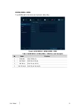
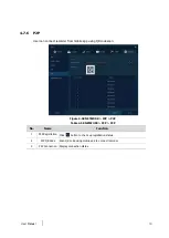
Page 92: ...app using QR code scan Figure 4 58 NETWORK P2P P2P Table 4 58 NETWORK P2P P2P No Name Function 1 P2P Registration Click button to check up registration status 2 P2P QR Code Scan QR code using mobile app to connect recorder 3 P2P Connection Display connection status ...

Page 93: ...unction 1 Notification Server Select deselect whether to use Notification Server 2 Type Select TCP or UDP Protocol 3 IP Enter the server IP address or host name 4 Port Enter the server port 5 Test Send a test message to the server to check the connection status Click Save button when the transmission is successful TCP can check the results in the recorder but UDP should be checked in the notificat...

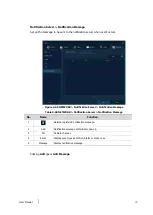
Page 94: ...Notification Server Notification Message Table 4 60 NETWORK Notification Server Notification Message No Name Function 1 Deleted registered notification message 2 Add Notification message edit window pop up 3 CH Camera channel 4 Event Display event type as Motion Alarm or Video Loss 5 Message Display notification message Clicking Add opens Add Message ...

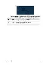
Page 95: ...er Notification Message Add Message Table 4 59 NETWORK Notification Server Notification Message Add Message No Name Function 1 CH Select the channel to add a message 2 Event Select the event type motion alarm video loss 3 Message Create a message to send ...

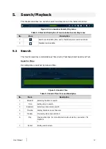
Page 96: ...h This function searches recorded data as Time Event Thumbnail Smart Search and Text Search Time Recording data is searched by date and time Figure 5 2 Search Time Table 5 2 Search Time Item and Description No Item Description 1 Calendar Selecting the date to search 2 Time Setting time to search 3 Bookmark Selecting a bookmark to search 4 Timeline Display timelines across channels 5 Preview Previe...

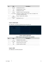
Page 97: ...ting the types of event immediate recording motion Alarm In Video Loss and bookmark 6 Search Searching the event 7 Event List Displaying event list searched 8 Thumbnail Field Displaying thumbnail images of selected event 9 Play Playing video clips selected For more information about Live bar see section 5 2 Playback 10 Cancel Ending search screen Search Thumbnail Recording data is searched and pla...

Page 98: ...hanging the time 6 Time Lapse Pause Playing or stopping videos searched 7 Cancel Ending search screen Search Smart Search Recording data is searched by detecting change of specific area Figure 5 5 Search Smart Search Table 5 5 Search Smart Search Item and Description No Item Description 1 CH Selecting channels to search 2 Area Setup Select area to search motion event 3 Start Setting starting time ...

Page 99: ...arch 5 Keyword Entering keyword to search 6 Case Sensitive Searching items in case sensitive 7 Whole Word Searching items that include all words 8 Search Searching the event 9 Event List Displaying event list searched 10 Thumbnail Field Displaying thumbnail images of selected event 11 Play Playing video clips selected For more information about Live bar see section 5 2 Playback 12 Cancel Ending se...

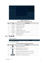
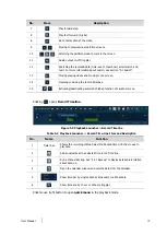
Page 100: ...bnail images of selected event 7 Play Playback selected event 8 Cancel Ending search screen 5 2 Playback To play recorded data Figure 5 8 Playback Launcher Table 5 8 Playback Launcher Item and Description No Item Description 1 Displaying present play status 2 Date and Time Displaying date and time of playing videos 3 Moving to the first section of the video 4 Playing the videos with multiplied spe...

Page 101: ...ing deactivating automatic hidden function of Launcher menu Clicking opens Record Timeline Figure 5 9 Playback Launcher Record Timeline Table 5 9 Playback Launcher Record Time Line Item and Description No Name Function 1 Time lines Shows the recording status Select the desired time with the mouse to playback 2 Add bookmarks at the selected time in the Time line 3 Run a Manual backup See 3 2 1 Back...

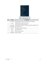
Page 102: ...d 4x4 2 Zoom in Magnify selected live screen 2x 4x and 8x This menu is shown full screen mode only 3 Text Overlay POS text overlay on the screen This menu is shown when enable Text menu 4 Speaker Output Recorded audio output 5 Go to Live Stop playback and return to live mode 6 Search Open Search window 7 Backup Open manual backup menu 8 Set Bookmark Save the bookmark ...

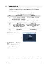
Page 103: ... CoreTM 2 Duo E7200 2 53GHz or higher RAM 2GB or higher 1 5GB or higher VGA ATI RadeonTM HD 3650 or NVIDIA GeForce 8400GS or higher 1280x1024 32bpp or Higher Multi Monitor ATI RadeonTM HD 2400 or NVIDIA GeForce FX5500 or higher 1024x768 24bpp or higher HDD Over 6GB Over 1GB LAN Gigabit Ethernet 10 100 Mbps Ethernet 1 Enter IP address of a recorder in Internet browser 2 Enter ID and Password and th...

Page 104: ...User Manual 100 In case of selecting Viewer Internet Explorer 1 Click Viewer 2 When Java download screen opens download and install JAVA 3 Live images may be monitored In case of selecting Viewer Chrome ...

Page 105: ...ser Manual 101 1 After click Viewer jnlp file can be downloaded Click Keep button 2 Click webviewer_chrome jnlp 3 When Java download screen opens download and install JAVA 4 Live images may be monitored ...

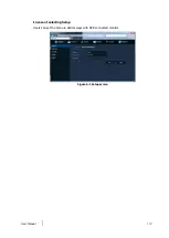
Page 106: ...User Manual 102 In case of selecting Setup Users can set the menu in similar ways with NVR connected monitor Figure 6 1 Setup screen ...

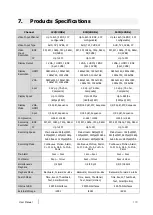
Page 107: ...Mode VGA HDMI 1 4 Split Sequence 1 4 9 16 Split PIP Sequence 1 4 9 Split PIP Sequence Spot 1 4 Split Sequence 1 16 Split Sequence 1 9 Split Sequence Compression H 264 H 265 H 264 H 265 H 264 H 265 Recording Resolution BNC 5M 4M 1080p 720p 960H 5M 4M 1080p 720p 960H 5M 4M 1080p 720p 960H IP Up to 3M Up to 3M Up to 3M Recording Speed Main stream 48fps 5M 60fps 4M 120fps 1080p Sub Stream 120fps VGA M...

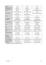
Page 108: ... Web Dashboard CMS Mobile Web Dashboard Audio 4 RCA Input 1 RCA 1HDMI Output 4 RCA Input 1 RCA 1HDMI Output 16 RCA Input 1 RCA 1 HDMI Output Alarm 4 Input 1 Output Terminal block 4 Input 1 Output Terminal block 16 Input 1 Output Terminal block Serial Port 2 RS485 Terminal block 2 RS485 Terminal block 2 RS485 Terminal block USB 3 USB Front 2 Rear 1 3 USB Front 2 Rear 1 3 USB Front 2 Rear 1 Operatin...

Reviews: