background image

Caution

Warning

Prohibition


which concerns the product and your personal safety.

The following symbols are very important. Please be sure to understand their meaning, 

Symbol Description

The installation, dismantlement and maintenance of the unit must be performed 
by qualified personnel. It is forbidden to do any changes to the structure of the 
unit. Otherwise injury of person or unit damage might happen.

Safety Precautions

Make sure the power supply to the heat pump unit is off before any operations are 
done on the unit. When the power cord gets loose or is damaged, always get a 
qualified person to fix it.

1

2. 

Safety Precautions

Before


Use

1

05

User Manual

Be


sure


to


read


this


manual


before


use

.

Keep


the


unit


away


from


the


combustible


or


corrosive


environment.

Before taking shower, please always 
add a mixture valve before water tap 
and set it to proper temperature. 

This appliance can be used by children aged from 8 years and above and persons 
with reduced physical, sensory or mental capabilities or lack of experience and 
knowledge if they have been given super visioner instruction concerning use of the
appliance in a safe way and understand the hazards involved. Children shall not play
with the appliance. Cleaning and user maintenance shall not be made by children 
without supervision.

1.

The heat pump is for “Closed pressurized water borne systems only, with 

running pressure from 1-2.5 bars”. 
2. Heat pump indoor unit should only be placed in a room with drainage in the floor. 
(If any catastrophic leak from the water tank, no costly damage to the house can be 
put on supplier).

Summary of Contents for GB 06

Page 1: ...GB 06 STM 06 GB 13 STM 13 GB 09 STM 09 SISTEMA SPLITTATO POMPA DI CALORE CON GRUPPO IDRONICO E SERBATOIO MANUALE DI INSTALLAZIONE USO E MANUTENZIONE 62403684 R01 08 10 2019_IT UK ...

Page 2: ...ema di installazione 2 3 Installazione dell 4 Installazione dell u 5 Connessione tubazione refrigerante 6 Connessione tubazione idraulica 7 9 Cablaggio Test funzionale nità esterna Installazione degli accessori 8 Degasazione circuito idraulico 20 27 31 32 34 37 38 40 41 4 20 3 Uso 1 4 Introduzione al pannello di controllo Istruzioni di funzionamento 3 Resistenze elettriche Lista degli errori 2 42 ...

Page 3: ...nterna esterna Assistenza Unità Unità Pulizia del filtro acqua Pulizia dello scambiatore Carica del gas Pulizia dello scambiatore a piastre Antigelo in inverno 4 Soluzione ai problemi 84 5 Schema Di Collegamento 92 84 85 85 86 88 88 88 89 89 89 90 103 Sommario ...

Page 4: ...caso di problemi contattare il venditore à Unità interna Elenco degli accessori 1 1 Elenco Degli Accessori Prima Dell utilizzo 104 Manuale di uso Kit di sicurezza Valvola di sicurezza Quantità 1pcs 1kit 1pcs 1pcs 2pcs Profilo decorativo ad L posteriore tipo 2 Profilo decorativo ad L posteriore tipo 1 Desccrizione Immagine ...

Page 5: ...cauzioni Di Sicurezza Prima Dell utilizzo 105 Manuale di uso Leggere questo manuale attentamente prima dell utilizzo Mantenere l unità lontana da ambienti corrosivi o incendiabili Acqua calda sanitaria Installare sempre una valvola miscelatrice adeguatamente tarata prima di ogni rubinetto Questo apparecchio persone con ridotta capacit fisiche mentali o sensoriali o con mancanza di o conoscenza se ...

Page 6: ...io utilizzare un idoneo interruttore per l apparecchio Assicurarsi che l alimentazione elettrica corrisponda alle specifiche altrimenti si potrebbero verificare gravi danni Lo smaltimento delle eventuali batterie esauste va effettuato negli appositi punti di raccolta Installare un interuttore differenziale RCD con corrente differenziale IΔn 30 mA ON OFF Ingresso acqua sanitaria Connessione al serb...

Page 7: ...e idonei Non utilizzare fili di rame o di acciaio in sostituzione del fusibile o dell interruttore si potrebbero verificare gravi danni Se il cavo elettrico appare deteriorato o rovinato farlo sostituire da personale qualificato Non toccare la griglia uscita aria metre la ventola è in funzione 1 2 Precauzioni Di Sicurezza Prima Dell utilizzo ...

Page 8: ... Maschio No 1 2 3 4 5 6 7 8 9 10 11 12 Ingresso acqua fredda per serbatoio G3 4 Maschio Uscita acqua calda sanitaria G1 Maschio Collegamento refrigerante da 1 4 1 2 6KW Collegamento refrigerante da 3 8 1 2 9KW Supporto per connessioni refrigeranti Passacavi Ingresso acqua per riscaldamento raffrescamento G1 Maschio Uscita acqua per riscaldamento raffrescamento G1 Maschio 13 14 15 16 17 18 19 Descr...

Page 9: ... Unità Interna 1 4 Ingombri E Dimensioni Prima Dell utilizzo 109 GB 06 09 13 Unit mm 1600 1720 1688 1202 1310 600 675 660 ...

Page 10: ...mensioni Prima Dell utilizzo Unità Esterna Unità mm 110 STM 06 Tubazione del gas O D 12 7 φ φ STM 09 φ φ Tubazione del liquido O D 6 35 Tubazione del liquido O D 9 52 Tubazione del gas O D 12 7 1 4 1 2 3 8 1 2 STM 06 09 ...

Page 11: ... Unità Esterna Unità mm 111 1195 1171 407 740 159 1058 1124 460 Tubazione del liquido O D 9 52 Tubazione del gas O D 16 φ φ 5 3 8 8 430 STM 13 1 4 Ingombri E Dimensioni Prima Dell utilizzo ...

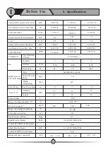
Page 12: ... Max 1 Assorbimento elettrico Min Max 1 C O P Min Max 2 Potenza massima in riscaldamento 2 C O P 2 Potenza riscaldamento Min Max 2 Assorbimento elettrico Min Max 2 C O P Min Max 3 Potenza massima in raffrescamento 3 E E R V Hz Ph KW W W Sistema Con Serbatoio Integrato KW W W W KW W W KW W W W KW W W GB 09 GB 13 220 240 50 1 R410A 10 10 4 03 4 33 10 10 975 2153 4 02 4 65 9 53 3 17 4 19 9 53 1230 29...

Page 13: ... elettrica incorporata Controllo della resistenza elettrica da 1 5 kW Resistenza elettrica incorporata Controllo della resistenza elettrica da 6 kW Connessione refrigerante Kg h inch Mpa K W KW inch 56 59 35 35 240 3 8 1 2 250 360 0 7 Tipo Quantità Sistema Quantità Portata Potenza nominale Twin Rotary 1 h Tipo Scambiatore a piastre Massima prevalenza m 7 5 7 5 Esterno Interno dB A Volume acqua Int...

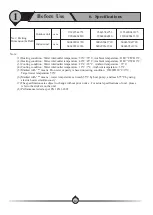
Page 14: ...ita 23 18 C temperatura ambiente 35 C 4 Condizione di raffrescamento Temperatura acqua ingresso uscita 12 7 C temperatura ambiente 35 C 5 La produzione di ACS è calcolata nelle seguenti condizioni DB WB 20 15 C temperatura impostata 50 C 6 La temperatura dell acqua può raggiungere i 55 C tramite la pompa di calore e I 75 C con l utilizzo simultaneo delle resistenze elettriche 7 Le specifiche posso...

Page 15: ... Circolatore Valvola a 3 vie 20 21 22 23 24 25 26 27 Quantità 1 1 1 1 1 1 1 1 1 1 1 1 1 1 Serbatoio acqua Serbatoio di espansione da 5 L Sensore di temperatura serpentino Sensore di temperatura acqua ingresso Sensore di temperatura acqua uscita Sensore di temperatura ambiente Sensore di temperatura acqua calda Sensore di temperatura MV1 Sensore di temperatura MV2 Connettore refrigerante da 1 4 6KW...

Page 16: ...lvola a 3 vie 16 17 18 19 20 21 22 23 24 25 26 1 1 1 1 1 1 1 1 1 1 1 1 1 1 Serbatoio acqua Serbatoio di espansione da 5 L Sensore di temperatura serpentino Sensore di temperatura acqua ingresso Sensore di temperatura acqua uscita Sensore di temperatura ambiente Sensore di temperatura acqua calda Sensore di temperatura MV1 Sensore di temperatura MV2 Connettore refrigerante da 3 8 Connettore refrige...

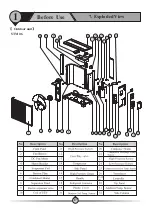
Page 17: ...117 1 7 Vista Esplosa Prima Dell utilizzo Unità Esterna STM 06 ...

Page 18: ... Ventola esterna Pannello frontale Supporto motore Angolare Valvola a 4 vie Guida aria Motore ventola 1 2 3 4 5 6 7 8 9 Scatola elettrica Coperchio scatola elettrica 10 11 Pannello superiore Maniglia Pannello posteriore Paratia Paratia Valvola 1 4 6KW 3 8 9KW Condensatore Compressore Riscaldatore compressore Piede Bobina EEV Riscaldatore condensatore Valvola di espansione elettronica EEV Pannello ...

Page 19: ...otore ventola Guida aria 31 32 1 2 3 4 5 6 7 8 9 Pannello superiore Sensore ti temperatura ambiente serpentino Condensatore 10 11 12 22 33 Paratia Compressore Maniglia Sensore di temperatura di aspirazione Pannello inferiore Piastra valvola Valvola 5 8 Sensore di temperatura scarico compressore Separatore liquido Valvola 3 8 Blocco connettori Carter resistenza PFC trasduttore Controllore EEV Risca...

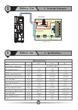
Page 20: ...a prestazione nei giorni freddi Utilizzando una valvola miscelatrice tra mandata calda acqua calda sanitaria e mandata media acqua calda sanitaria si possono raggiungere le migliori prestazioni senza compromettere la portata massima di acqua calda sanitaria 2 1 Metodi Di Installazione Installazione 120 Temperatura esterna to Temperatura media to 0 40 0 95 Temperatura dell ambiente di stoccaggio ...

Page 21: ... soluzione è in grado di scaldare un volume d acqua inferiore rispetto ad altre soluzioni I vantaggi sono A La pompa di calore è collegata direttamente al serbatoio per cui la portata d acqua sarà facilmente assicurata B Non serve un processo di sanificazione perchè l acqua è scaldata passando direttamente nel serpentino Questo fa risparmiare energia 1 Applicazione 1 Ritorno dalla pompa di calore ...

Page 22: ...di un serbatoio di accumulo tra pompa di calore ed impianto permette di 1 Avere una portata di acqua stabile e sufficiente 2 Accumulare calore per minimizzare le fluttuazioni durante le fasi di carica 3 Aumentare il volume d acqua per permettere un ottimale funzionamento della pompa di calore Se la quan accumulo volume tità e la portata d acqua del circuito sono sufficienti per permettere un buon ...

Page 23: ...rbatoio di accumulo Rilevatore sensori Flussostato Articolo 12 13 14 15 16 17 18 19 20 21 22 23 Descrizione 2 1 Metodi Di Installazione Installazione Sensore di temperatura acqua in uscita Sensore di temperatura acqua calda Valvola motorizzata a 3 vie Acqua di ritorno dal circuito di riscaldamento raffrescamento Rubinetto scarico Kit di sicurezza Serbatoio di accumulo Valvola di miscelazione 1 0 1...

Page 24: ...camento circuito 2 impostato in OFF 2 1 4 Riscaldamento raffrescamento circuito 1 Controllo della valvola miscelatrice MV1 Se la temperatura dell acqua nel sistema 1 è superiore inferiore rispetto alla temperatura che serve nel circuito 1 in riscaldamento raffrescamento si può aggiungere una valvola miscelatrice collegandola alla porta MV1 sull unità interna Il sistema controllerà la valvola misce...

Page 25: ...postazioni è impostata la voce valvola miscelatrice l unità mostrerà un codice di errore Suggerimenti Generalmente se la temperatura dell acqua nel circuito è superiore inferiore rispetto alla temperatura che serve nel circuito in riscaldamento raffrescamento è necessario aggiungere una valvola miscelatrice A Se il sistema ha due circuiti le temperature impostate possono essere diverse Ovviamente ...

Page 26: ...rbatoio di accumulo è impostato sia P1 che P2 lavoreranno quando ci sarà richiesta di riscaldamento o raffrescamento come impostato e seguiranno queste regole La pompa funzionerà solo se la temperatura misurata nel serbatoio di accumulo tramite Tc 20 C in riscaldamento La pompa funzionerà solo se la temperatura misurata nel serbatoio di accumulo tramite Tc 23 C in raffrescamento Per esempio se P1 ...

Page 27: ...di calore Rete elettrica PE N1 L1 N1 L1 PE Ingresso alimentazione per riscaldatore ausiliario per ACS Uscita alimentazione per riscaldatore ausiliario per ACS K2 2 C Alimentazione elettrica per unità esterna 3x2 5mm uscita L unità esterna deve essere collegata a questi terminali per ricevere l alimentazione elettrica D Alimentazione elettrica libera 220V 50Hz P 100W E F G Pompa dell acqua E Circol...

Page 28: ...pa di calore Rete elettrica N2 L2 G Ingresso alimentazione elettrica AH ed HBH Uscita alimentazione elettrica AH ed HBH K1 N2 L2 G 128 Lato Applicazione B A G 24VCOM 1 G 24VCOM 2 A B C COM ES COM CS COM HS COM TH D G F E A Cavo di comunicazione verso l unità esterna Collegare A e B rispettivamente ad A e B sull unità esterna B C Valvole motorizzate 1 2 Come spiegato nel capitolo illustrazioni di s...

Page 29: ... ore di punta Se si desidera che l unità smetta di funzionare durante è possibile collegare il segnale della compagnia elettrica a questi terminali Arresto esterno e utilizzare à Quando sono collegati 2 circuiti di riscaldamento l unit più alta tra I due circuiti quando questi sono in riscaldamento e la Però se il circuito impostato a temperatura selettiva non ha richiesta o ha gi raggiunto la sua...

Page 30: ... essere fissati saldamente n far toccare I cablaggi insieme ssicurarsi che l alimentazione di rete sia conforme ai dati di targa Assicurarsi che la potenza il cablaggio e la presa di alimentazione siano conformi alla potenza richiesta dall unità 2 Collegamento elettrico Schema di installazione Cavo di segnale tra unit interna ed esterna à Cavo di alimentazione tra unit interna ed esterna à Aliment...

Page 31: ... ventilato F L unit interna non può essere installata in un ambiente con la presenza di liquidi o gas volatili corrosivi o infiammabili G Durante il trasporto mantenere l unit interna verticale Inclinarla oltre i 30 rischia di farla cadere con rischi per l unit stessa e per le persone vicine H I Attorno all unit interna deve essere lasciato sufficiente spazio per le operazioni di manutenzione e pe...

Page 32: ...re che la neve occluda l aspirazione e lo scarico dell aria F Assicurarsi che ci sia possibili di drenaggio attorno all per evacuare la condensa durante il processo di sbrinamento G Durante l installazione inclinare la macchina di 1 cm m per favorire lo scarico dell acqua piovana dovrebbe essere installata in un ambiente non umido e non corrosivo per non accorciarne la vita di funzionamento J Atto...

Page 33: ...stalla in condizioni climatiche severe neve umidit è raccomandato installare ad almeno 50 cm da terra 4 Le dimensioni della base devono essere almeno come quelle dell unit 5 E consigliato l uso di gommini assorbi vibrazioni 6 Assicurarsi che attorno all ci sia sufficiente spazio per fare manutenzione agevolmente L l l unit unit unit unit à deve à à à à à 50cm A Se è necessario montare l unità a pa...

Page 34: ...l cavo il collegamento tra le due unit NOTA Non rimuovere il coperchio di plastica dal tubo prima di iniziare l installazione à Precauzione Prima di forare assicurarsi di non incontrare ostacoli dove si intende forare se si hanno dubbi utilizzare un rilevatore di tubi e cavi Fare un primo foro con una punta da 12 15 mm e successivamente fare un foro di circa 80 mm di diametro Utilizzare una veloci...

Page 35: ...iquido B 5 8 valvola gas Inserimento dei tubi IMPORTANTE Svolgere il tubo dall interna verso quella esterna e collegare i raccordi Il raggio di curvatura non deve essere inferiore a 15 cm la curvatura deve essere graduale non utilizzare spigoli o gli angoli dei muri Usare la dima di cartone per verificare il corretto raggio di curvatura Fare passare il cavo di alimentazione insieme ai tubi unità R...

Page 36: ...i sulle valvole 136 3 Preparare la pompa del vuoto ed il manometro collegare un tubo del manometro alla pompa del vuoto 4 Collegare l altro tubo 5 Aprire il manomentro edavviare la pompa del vuoto per circa 10 minuti Quando il manomentro indica una pressione negativa chiudere il manomentro e spegnere la pompa Attenzione Per allentare I connettori usare due chiavi contemporaneamente Quando si colle...

Page 37: ...tazione alvola a sfera è raccomandata per semplificare lo scarico e la pulizia del filtro Alimentazione acqua sanitaria Filtro Tubo di scarico Connessione al serbatoio acqua Valvola di non ritorno Valvola a sfera Dopo aver installato l Selezionare con cura le tubazioni utilizzate Dopo la connessione le tubature devono esere testate in pressione e pulite prima dell uso unità collegare l acqua in in...

Page 38: ...egare ad uno della casa scarico 2 7 Installazione Del Kit Degli Accessori Installazione 138 2 Il kit di sicurezza include una valvola di sicurezza pressione temperatura un degasatore ed un manometro Assicurarsi che questi componenti siano presenti negli accessori 1 Prendere il kit di sicurezza dagli accessori 2 Applicare del nastro sigillante sui filetti da 1 connettore maschio sotto al serbatoio ...

Page 39: ...re corto Individuare I 14 fori per le viti di fissaggio 3 Posiziona I due profili lunghi sul lato destro e sinistro posteriore dell apparecchio ed il profilo corto sul lato posteriore superiore Stringere le viti Riferirsi alle immagini 3 e 4 4 Finito verificare attraverso la figura 5 unità utilizzando i profili posteriori di 2 1 2 2 Installazione 139 3 4 5 2 Profilo decorativo posteriore lungo ad ...

Page 40: ...e le valvole a sfera 1 e 2 e svitare il piccolo tappo della valvola di degasazione 17 2 Il degasatore fa fuoriuscire l aria fino a che non arriva solo acqua senza aria 3 Chiudere la valvola 2 Evacuazione aria dal circuito di riscaldamento 1 Aprire le valvole 1 2 9 10 11 12 13 14 15 16 e svitare il tappino del degasatore 18 per riempire completamente il circuito 2 Quando l acqua fuoriesce dalla val...

Page 41: ...nuti senza problemi il primo avvio ultimato In caso contrario fare riferimento al capitolo assistenza e manutenzione per risolvere questi problemi è bene portare a termine alcuni controlli per assicurarsi che l unità possa lavorare nel miglior modo possibile L elenco seguente non è completo è solo l elenco minimo dei controlli da portare a termine unità è completata le tubazioni sono collegate e d...

Page 42: ...ttamente Quando il simbolo è grigio la comunicazione è interrotta B Modo Di Funzionamento Quando la relativa modalità di funzionamento è attiva il simbolo sarà attivo se abbiamo diverse modalità attive il simbolo mostrerà la modalità operativa in quel momento Acqua calda sanitaria Riscaldamento Raffrescamento Modalità sbrinamento Modalità risparmio Modalità interruzione Modalità serbatoio acqua ca...

Page 43: ...ntità del refrigerante nel circuito verificando la pressione sull evaporatore C Controllare che la temperatura ambiente non sia inferiore a 15 C Portata acqua troppo bassa Significa che la portata d acqua del circuito è inferiore al minimo valore permesso Controllare il circuito il filtro e il funzionamento della pompa Errore nel flusso stato Il flussostato deve essere aperto mentre la pompa di ci...

Page 44: ...rrore di sbrinamento Se l unità non completa l attività di sbrinamento per 3 volte consecutive si blocca ed appare l errore codice S08 Per ripristinare la macchina togliere e ridare l alimentazione elettrica Verificare che la temperatura attuale dell acqua non sia troppo bassa per portare a termine l attività di sbrinamento in questo caso lo scambiatore a piastre si potrebbe congelare Inizializzaz...

Page 45: ...n funzione dei parametri impostati Pannello Touch Screen Modalità Di Funzionamento 34 7 23 9 6 8 15 26 Modalità di funzionamento temperatura corrente dell acqua Temperatura dell acqua impostata Temperatura esterna Temperatura serbatoio Temperatura ambiente START ENGING STOP 34 7 23 9 6 8 15 26 START ENGING STOP 34 7 23 9 6 8 START ENGING STOP 40 35 Temperatura dell acqua impostata 3 Uso 1 Introduz...

Page 46: ...ni 1 Circuito 1 riscaldamento raffrescamento Vedi pag 47 5 Riduzione Temp mandata per riscaldamento Vedi pag 55 Vedi pag 71 2 Circuito 2 riscaldamento raffrescamento Vedi pag 50 3 Impostazioni acqua calda sanitaria Vedi pag 51 Vedi pag 70 4 Impostazioni accumulo acqua calda sanitaria Vedi pag 53 6 Funzione anti legionella Vedi pag 56 7 Modalità vacanza Vedi pag 57 8 Impostazioni di uso Vedi pag 58...

Page 47: ...o Questa impostazione serve a far riavviare l unità L unità partirà quando raggiungerà Tset 1 01 in riscaldamento oppure Tset 1 01 in raffrescamento Entrambe le impostazioni sono basate sul Δ T Per esempio in riscaldamento se Tset 48 mentre 1 01 2 e 1 02 1 quando la temperatura misurata sar oltre 50 C Tset 1 01 l unità si fermerà Quando la temperatura scenderà sotto i 47 C Tset 1 02 l unità ripart...

Page 48: ...mperatura di mandata ideale in funzione della temperatura ambiente Quando la funzione è attiva l unità modifica la temperatura di mandata tanto che sia impostata o che sia calcolata tramite la curva di riscaldamento in accordo con la differenza che c è tra la temperatura impostata nell ambiente e la temperatura misurata 1 16 Correzione temperatura di mandata Impostare On o OFF 1 17 Valore temp amb...

Page 49: ...ergetico molto basso Si consiglia di impostare un valore che permetta un mantenimento della temperatura al minimo della velocità possibile senza spegnimenti Per esempio in riscaldamento se Tset 45 C e 1 03 2 C il compressore lavorerà al massimo fino a raggiungere 43 C Successivamente rallenterà se anche lavorando al minimo la temperatura supererà Tset 1 01 il compressore si spegnerà 1 04 Impostazi...

Page 50: ...on serve impostare il parametro 2 05 OFF successivamente impostare il parametro fisso della temperatura in riscaldamento tramite il parametro 2 03 Impostazione temperatura per riscaldamento 2 06 2 10 2 06 Temperatura acqua A Temperatura esterna 1 2 07 Temperatura acqua B Temperatura esterna 2 2 08 Temperatura acqua C Temperatura esterna 3 2 09 Temperatura acqua D Temperatura esterna 4 2 10 Tempera...

Page 51: ... il riscaldatore ausiliario per acqua calda sanitaria HWTBH o entrambi interverranno singolarmente o insieme per aiutare la pompa di calore nella produzione di acqua calda sanitaria 3 04 Temperatura di intervento della gestione delle priorità Questo valore è la temperatura sotto la quale il sistema attiverà la gestione delle priorità sotto a questa temperatura l unità cercherà di trovare un bilanc...

Page 52: ...empo 3 05 La temperature di mandata riscaldamento è scesa sotto 3 07 Se l unità lavora in riscaldamento oltre 3 06 Il tempo Massimo di riscaldamento è raggiunto L unità passa alla produzione di ACS ed inizia a contare L unità continua a lavorare in riscaldamento e continua a contare L unità lavora in riscal damento YES NO YES YES YES YES NO NO Il tempo limite di funzionamento per acqua calda sanit...

Page 53: ...l unità funzionerà con temperatura impostata 3 01 all interno di questo periodo Si possono impostare diversi periodi di funzionamento per ogni giorno della settimana 4 03 Funzione riscaldamento ACS ridotto Abilita la funzione riscaldamento 4 04 Timer funzione riscaldamento ACS ridotto Impostare il periodo di funzionamento della funzione riscaldamento entro questo periodo l unità lavorerà con l imp...

Page 54: ... periodo impostato in 4 04 la temperatura impostata sarà il valore introdotto 4 06 Impostazione ΔT temperatura riscaldamento ridotto Impostare ΔT riscaldamento riavvio Quando la temperatura dell acqua scende sotto al valore di ΔT impostato e siamo dentro al periodo impostato in 4 04 l unità si riavvia 3 Uso 2 Istruzioni Di Funzionamento 154 ...

Page 55: ...ne riduzione setpont entro questo periodo l unità lavorerà con l impostazione di temperatura di mandata ridotta Per ogni giorno della settimana si possono impostare diversi periodi 5 04 Funzionamento silenzioso Abilita il funzionamento silenzioso 5 05 Temp di deriva ammessa Impostare la massima temperatura di deriva durante il funzionamento silenzioso Durante il funzionamento silenzioso i compress...

Page 56: ...i legionella 6 02 Giorno e ora Imposta a che ora e in che giorno attivare la funzione anti legionella 6 03 Setpoint Imposta la temperatura da raggiungere per la funzione anti legionella Riferirsi sempre alla norma locale vigente per la corretta impostazione di questa temperatura 6 04 Durata Imposta il tempo al quale la temperatura deve rimanere in maniera continuativa al valore impostato 6 05 Temp...

Page 57: ...a modalità vacanze Imposta il ΔT da togliere alla temperatura impostata per la produzione di ACS durante la permanenza della modalità vacanze 7 03 ΔT su temperatura mandata durante la modalità vacanze Imposta il ΔT da togliere alla temperatura di mandata impostata durante la permanenza della modalità vacanze Data inizio modalità vacanze Imposta la data di inizio vacanze 7 05 Data fine modalità vac...

Page 58: ...può essere modificato da questo menu Per attivare questo menu serve una password 8 02 Riscaldamento raffrescamento Timer on off Per abilitare il timer per riscaldamento raffrescamento 8 03 Riscaldamento raffrescamento Timer on off Impostare gli avvii e gli spegnimenti del riscaldamento raffrescamento Si possono impostare diversi avvii all interno dello stesso giorno 3 Uso 2 Istruzioni Di Funzionam...

Page 59: ...umulo oppure in un suo punto ideale 8 07 Salvataggio delle impostazioni attuali Questo parametro è usato dall installatore per salvare le impostazioni correnti come impostazioni dell installatore Così l installatore può ricaricare il salvataggio nel sistema se necessario 8 08 Caricamento impostazioni salvate Caricare le impostazioni salvate 8 09 Ripristino alle impostazioni di fabbrica Ripristinar...

Page 60: ...parametro è usato per impostare il funzionamento di base come il controllo delle temperature dell acqua o la temperatura ambiente Quando il funzionamento di base è attivo il sistema prende la temperatura ambiente come oggetto di controllo NON CONSIGLIATO Quando il funzionamento di base è non attivo il sistema prende la temperatura di mandata come oggetto di controllo CONSIGLIATO Il riscaldamento e...

Page 61: ...o automatico tra riscaldamento e raffrescamento non è attivo Per evitare conflitti assicurarsi che le funzioni di riscaldamento e raffrescamento non siano attive contemporaneamente per cui se è attivo il controllo tramite segnale esterno assicurarsi che il segnale di chiamata riscaldamento e raffrescamento non siano attive contemporaneamente 9 07 Avvio riscaldamento da sonda ambiente Questo parame...

Page 62: ...dato da un riscaldatore ausiliario per ACS sul serbatoio di accumulo HWTBH Priorità per riscaldatore ausiliario esterno per ACS Impostare la priorità del riscaldatore ausiliario esterno HWTBH rispetto alle resistenze interne all unità interna HB Se l unità è in funzionamento di riscaldamento ACS e la potenza erogata non è sufficiente verrà avviata anche una fonte aggiuntiva AH o HWTBH automaticame...

Page 63: ...te il parametro 10 4 Se la temperatura impostata e misurata nel serbatoio di ACS è superiore rispetto alla temperatura massima raggiungibile dalla pompa di calore il riscaldatore ausiliario HWTBH funzionerà da solo mentre la pompa di calore lavorerà in riscaldamento o raffrescamento domestico in accordo con la richiesta Se la temperatura misurata nel serbatoio di ACS è inferiore rispetto alla temp...

Page 64: ...tore è sempre in funzione 3 OFF con compressore P0 si spegne quando il compressore si spegne Intervallo di spegnimento 11 5 Tempo di ON Se il modo di funzionamento del circolatore P0 è ad intervalli il circolatore si spegnerà quando il compressore si spegnerà ma si riavvierà per il tempo impostato in 11 5 ad intervalli impostati in 11 11 6 Serbatoio di accumulo 11 7 Circolatore P1 per funzione ris...

Page 65: ...emperatura e della durata della fase 1 della funzione asciugatura massetto Asciugatura massetto temperatura impostata nella fase 2 12 5 Asciugatura massetto durata della fase 2 Impostazione della temperatura e della durata della fase 2 della funzione asciugatura massetto 12 6 Durata della funzione asciugatura massetto 12 7 Temperatura massima raggiunta durante l asciugatura del massetto Questi due...

Page 66: ...mposta il tipo di segnale proveniente dalla compagnia elettrica normalmente aperto significa che l unità deve lavorare normalmente se il segnale è presente contatto chiuso e spegnersi se il segnale scompare contatto aperto Normalmente chiuso è il contrario 13 3 HBH Riscaldatore ausiliario durante blocco elettrico Se ad esempio il riscaldatore ausiliario è una caldaia a gas si può abilitare la funz...

Page 67: ...di ACS alla posizione di riscaldamento raffrescamento 14 3 Recupero refrigerante Questa funzione può essere utilizzata dall installatore per recuperare tutto il refrigerante dentro al condensatore per scopi di manutenzione Quando attivato l unità forza il funzionamento in raffrescamento per determinato tempo 14 4 Retroilluminazione pannello di controllo Imposta la retroilluminazione del pannello t...

Page 68: ...azione tra i circuiti durante l antigelo Se la temperatura dell acqua è troppo bassa il condensatore rischia di congelare e potrebbe causare la rottura dell intero sistema Quindi se durante la funzione antigelo la temperatura dell acqua è troppo fredda l unità controllerà la temperatura dell acqua nell altro circuito Se la temperatura nell altro circuito è sufficientemente calda il sistema passerà...

Page 69: ...mperatura acqua riscaldamento raffrescamento 08 Portata acqua 09 Velocità del compressore 10 Apertura EEV 11 TA Temperatura esterna 12 Temperatura esterna media dell ultima ora 13 Temperatura esterna media delle ultime 24 ore 14 Pd Alta pressione 15 Ps Bassa pressione 16 Td Temperatura di scarico 17 Ts Temperatura aspirazione 18 Tp Temperatura esterna batteria 19 NA 20 NA 21 Velocità ventola 1 22 ...

Page 70: ...e attuale Lista degli errori precedenti TW Temperatura acqua per serbatoio di accumulo sanitario TC Temperatura acqua per serbatoio di accumulo tecnico TR Temperatura ambiente TA Temperatura esterna Visualizzazione dettagli codice di errore selezionato 3 Uso 2 Istruzioni Di Funzionamento 170 ...

Page 71: ...6 3 Uso 2 Istruzioni Di Funzionamento Questa unità include due resistenze elettriche interne Queste resistenze sono usate per riscaldare l acqua quando la potenza della pompa di calore non è sufficiente nel caso si voglia raggiungere la temperatura in maniera più veloce o nel caso in cui la pompa di calore non possa lavorare 171 ...

Page 72: ...l tempo determinato Fare riferimento al capitolo 3 10 Riscaldatore ausiliario 2 Se il valore di temperatura dell acqua sanitaria è inferiore al valore impostato nel termostato meccanico presente nell unità Facendo in questo modo il termostato meccanico funziona come termostato limite per evitare che la pompa di calore faccia partire le resistenze quando non desiderato 1 5KW Resistenza Elettrica Pe...

Page 73: ...ta anche la seconda resistenza 2 Se la temperatura dell acqua di riscaldamento è inferiore al valore impostato nel termostato elettronico Facendo in questo modo il termostato elettronico funziona come termostato limite per evitare che la pompa di calore faccia partire le resistenze quando non desiderato 173 Termostato Elettronico Termostato Elettronico 1 Premere per 3 secondi per avviare il termos...

Page 74: ...alimentazione elettrica 1 Compressore fermo troppo alta o troppo bassa oppure il sistema lavora oltre il carico massimo ammesso Il sistema si ripristina automaticamente dopo 5 minuti Se lo stesso errore si verifica 3 volte consecutivamente in un certo lasso di tempo il sistema si blocca definitivamente Verificare che l alimentazione elettrica sia corretta Verificare che I motori delle ventole o de...

Page 75: ...essore rimane avviato Se l unità lavora a bassa velocità per molto tempo si attiverà questa protezione automaticamente per permettere all olio di ritornare nel compressore Questa è una protezione normale di buon funzionamento che non necessità di alcuna azione Il compressore si Se la pressione dell impianto non è corretta Il sistema si ripristina autonomamente dopo 5 minuti Se lo stesso errore si ...

Page 76: ...ssa si attiva la resistenza del carter del compressore prima che il compressore venga avviato per portarlo alla corretta temperatura P08 Temperatura di scarico compressore troppo alta 8 Compressore fermo Controlla che la temperatura di mandata acqua non sia troppo alta soprattutto se la temperatura esterna è bassa controlla che la portata d acqua dell impianto sia sufficiente Controlla che ci sia ...

Page 77: ... tra mandata e ritorno sia abbastanza contenuta entro gli 8 C circa F01 Guasto alla sonda esterna 17 Compressore fermo Controlla che la sonda non sia in corto aperta e che non dia valori sbagliati Eventualmente sostituire la sonda F02 Guasto alla sonda della batteria di evaporazione 18 Compressore fermo Controlla che la sonda non sia in corto aperta e che non dia valori sbagliati Eventualmente sos...

Page 78: ... una pressione troppo bassa per 3 volte in un certo lasso di tempo appare questo messaggio Il sistema si ripristina togliendo e ridando alimentazione elettrica Verificare che il refrigerante nel sistema sia sufficiente Verificare che i motori delle ventole o della pompa funzionino regolarmente Verificare che il condensatore funzioni regolarmente Verificare che l EEV funzioni regolarmente Verificar...

Page 79: ...i controllo e PCB esterno o interno fallita verificare il cablaggio elettrico Verificare che gli ultimi 3 swith sul PCB esterno siano su 001 e che gli ultimi 4 sull unità interna siano settati a 1000 Il sistema riparte non appena la comunicazione sarà ripristinata E02 Comunicazione assente tra pannello di controllo esterno e relativo PCB 34 Compressore fermo Verificare il cablaggio E03 Errore sull...

Page 80: ...asto alla sonda di temperatura acqua calda sanitaria 3 Unità bloccata Controlla che la sonda non sia in corto aperta e che non dia valori sbagliati Eventualmente sostituire la sonda F15 Guasto alla sonda di temperatura acqua riscaldamento o raffrescamento 6 Unità bloccata Controlla che la sonda non sia in corto aperta e che non dia valori sbagliati Eventualmente sostituire la sonda F16 Guasto alla...

Page 81: ...verificare che il circolatore non sia rotto F29 Errore sulla valvola miscelatrice 1 17 Unità attiva valvola miscelatrice 1 bloccata su 0 Verificare il cablaggio della valvola miscelatrice 1 verificare la tensione del segnale in uscita dalla scheda PCB verificare che la valvola non sia rotta F30 Errore sulla valvola miscelatrice 2 18 Unità rimane attiva valvola miscelatrice 2 bloccata su 0 Verifica...

Page 82: ...ita verificare il cablaggio elettrico Verificare che gli ultimi 3 swith sul PCB esterno siano su 001 e che gli ultimi 4 sull unità interna siano settati a 1000 Il sistema riparte non appena la comunicazione sarà ripristinata S06 Temperatura acqua troppo bassa in modalit à raffrescamento Compressore fermo Il compressore si ferma se l acqua in uscita ha una temperatura inferiore ai 5 C in raffrescam...

Page 83: ... C Questa funzione serve per al compressore S10 Errore portata acqua troppo bassa Compressore fermo Se l unità si blocca per l errore S2 portata acqua troppo bassa per 3 volte in un certo lasso di tempo si ribloccherà ed apparirà S10 Togliere e ridare corrente elettrica per ripristinare l errore Verificare il circuito idraulico in particolare il filtro Verificare il buon funzionamento della pompa ...

Page 84: ...esterna Operazione da eseguirsi ogni 4 6 mesi E Se l ambiente di lavoro con detergenti specifici professionali per garantire le prestazioni e l efficienza ottimale F Si prega di prestare attenzione all ambiente circostante per assicurarsi che sicura e che l aspirazione e lo scarico dell aria non siano ostruiti G Tranne nel caso in cui la pompa abbia problemi non sono necessarie o assistenza all H ...

Page 85: ... 185 1 Manutenzione Del Controller b Rimuovere la cover superiore vedi figura a c Rimuovere il coperchio della scatola elettrica vedi figura b d Fare le necessarie attivit di manutenzione alla esterna vedi figura c a Togliere l alimentazione elettrica unità à 4 Cover Superiore Coperchio Scatola Elettrica a b c Valvola Di Manutenzione Usata principalmente per svuotare l impianto del gas refrigerant...

Page 86: ...rrore LED lampeggiante 0 5 secondi ON 2 secondi OFF 4 JP404 per riprogrammare la EEPROM dopo la programmazione è 5 Connettore per software di aggiornamento 6 Dip switch sulla scheda esterna 7 8 LED di stato della scheda drive esterna Durante il normale funzionamento lampeggia 2 secondi ON 2 secondi OFF Impostazioni di fabbrica necessario rimuovere il jumper Impostazioni di fabbrica ON OFF Scheda E...

Page 87: ... l intero motore fig g h i j f Sostituire il motore ventola e ripercorrere i passi precedenti al contrario h g j 图i Cavo Di Terra Cavo collegato al PCB Cavo collegato al condensatore del motore Rimuovere il motore a Rimuovere la ventola come nella procedura precedente 4 6 2 b Rimuovere la staffa di fissaggio della resistenza elettrica fig a c Scollegare il connettore rapido di alimentazione e rimu...

Page 88: ...lire la superficie delle alette da polvere carta plastica o altro B Utilizzare una spazzola morbida in plastica ed acqua per ripulire le alette dal materiale C Lasciare asciugare il tutto Attenzione Prima di pulire assicurarsi che la macchina sia disalimentata Non versare acqua sulle parti in tensione Utilizzare dei guanti durante l operazione di pulizia per evitare di tagliarsi a contatto con le ...

Page 89: ...a del sistema L attività deve essere eseguita da personale qualificato più refrigerante del necessario per evitare malfunzionamenti o blocchi per alta pressione può provocare blocchi per alta pressione danni all impianto e abbassa il rendimento del sistema Grazie alla grande turbolenza interna allo scambiatore abbiamo un effetto autopulente Tuttavia in determinati casi la tendenza a sporcarsi è mo...

Page 90: ...uirlo Sostituire il refrigerante con del prodotto nuovo e nella giusta quantità Sostituire il refrigerante con del prodotto nuovo e nella giusta quantità Verificare la portata d acqua nel circuito eventualmente utilizzare un apompa più performante Assicurarsi che la sonda di temperatura mandata acqua lavori adeguatamente 1 Nessuna alimentazione elettrica 2 Il fusibile è intervenuto o l interruttor...

Page 91: ...Sostituire il filtro disidratatore Ripararla o sostituirla Perdita di refrigerante Verificare che non ci siano perdite nell unità e nell impianto eventualmente ripararle Sostituire il refrigerante con del prodotto nuovo e nella giusta quantità Guasto al sensore sulla batteria di espansione Controllare la posizione ed il valore della sonda di temperatura eventualmente sostituire il sensore La venti...

Page 92: ...tà Interna 5 1 Schema Di Collegamento Schema Di Collegamento 192 ATTENZIONE Le specifiche possono subire modifiche senza preavviso Per le specifiche correnti consultare le etichette poste sul prodotto GB 06 ...

Page 93: ...tà Interna 5 1 Schema Di Collegamento Schema Di Collegamento 193 GB 09 ATTENZIONE Le specifiche possono subire modifiche senza preavviso Per le specifiche correnti consultare le etichette poste sul prodotto ...

Page 94: ...Unità Esterna 194 5 1 Schema Di Collegamento Schema Di Collegamento ATTENZIONE Le specifiche possono subire modifiche senza preavviso Per le specifiche correnti consultare le etichette poste sul prodotto ...

Page 95: ...nstallation 1 2 Wiring 3 Installation of the indoor unit 4 Installation of the outdoor unit 5 Refrigerant pipe connection 6 Water Pipe Connect 7 9 Test Run Installation methods Installation of the accessories 8 Air purging of water system 20 27 31 32 34 37 38 40 41 4 20 3 Use 1 4 Failure Code Introduction of operation panel Operation instruction 3 Electric Heater 2 42 102 42 47 72 75 ...

Page 96: ...tenance 2 Service Indoor unit Outdoor unit Cleaning of water filter Cleaning of heat exchanger Gas charging Cleaning of plate exchanger Antifreeze in winter 4 Trouble Shooting 79 5 Wiring Diagram 86 79 80 80 80 83 83 83 84 84 84 85 Catalogue 103 ...

Page 97: ...ny shortage or damage please contact local distributor Indoor unit List of accessories 1 1 List Of Accessories Before Use 104 User manual Four way Safety valve kit Pressure release valve Quantity 1pcs 1set 1pcs 1pcs 2pcs L type decorative panel in back side 2 L type decorative panel in back side 1 ...

Page 98: ...ore use Keep the unit away from the combustible or corrosive environment Before taking shower please always add a mixture valve before water tap and set it to proper temperature This appliance can be used by children aged from 8 years and above and persons with reduced physical sensory or mental capabilities or lack of experience and knowledge if they have been given super visioner instruction con...

Page 99: ...tion on the product which will lead to low efficiency or even non operation of this unit Main Power Cable RCD Indoor unit It is mandatory to use a suitable circuit breaker for the heat pump and make sure the power supply to the heater corresponds to the specifications Otherwise the unit might be damaged Disposal of Scrap Batteries Please discard the batteries as sorted municipal waste at the acces...

Page 100: ...lease select the correct fuse or breaker as per recommended Steel wire or copper wire cannot be taken as substitute for fuse or breaker Otherwise damaged maybe caused When the power cord gets loose or is damaged always get a qualified person to fix it Do not touch the air outlet grill when fan motor is running ...

Page 101: ... 1 Maintenance Valve L Type Back Decorative Board 2 Water Filling Port To Tank G3 4 Male High Temperature Sanitary Water Outlet G1 Male Refrigerant Connector 1 4 and GB 06 1 2 Refrigerant Connector 3 8 and GB 09 1 2 Support Base Of Refrigerant Connector Cable Gland Water Inlet From Heating Cooling System G1 Male Water Outlet From Heating Cooling System G1 Male 14 15 16 17 18 19 Superiore 2 1 7 5 6...

Page 102: ... Indoor unit 1 4 Outlines And Dimensions Before Use 109 GB 06 09 13 Unit mm 1600 1720 1688 1202 1310 600 675 660 ...

Page 103: ...1 4 Outlines And Dimensions Before Use Outdoor unit Unit mm 110 Liquid pipe O D 9 52 Gas pipe O D 12 7 φ φ 3 8 1 2 STM 06 09 STM 09 Liquid pipe O D 6 35 Gas pipe O D 12 7 φ φ 1 4 1 2 STM 06 ...

Page 104: ...1 4 Outlines And Dimensions Before Use Outdoor unit Unit mm 111 1195 1171 407 740 159 1058 1124 460 Liquid pipe O D 9 52 Gas pipe O D 16 φ φ 5 3 8 8 430 STM 13 ...

Page 105: ...in Max 1 C O P Min Max 2 Max Heating Capacity 2 C O P 2 Heating Capacity Min Max 2 Heating Power Input Min Max 2 C O P Min Max 3 Max Cooling Capacity 3 E E R V Hz Ph KW W W All In One Series KW W W W KW W W KW W W W KW W W GB 09 GB 13 220 240 50 1 R410A 10 10 4 03 4 33 10 10 975 2153 4 02 4 65 9 53 3 17 4 19 9 53 1230 2990 3 12 3 55 6 84 2 09 12 6 3 89 4 2 12 6 926 3072 3 89 4 77 11 5 3 08 3 76 11...

Page 106: ...uilt Electric Heater Control of 1 5KW electric heater Inbuilt Electric Heater Control of 6KW electric heater Refrigerant pipe connection Kg h inch Mpa K W KW inch 56 59 35 35 240 3 8 1 2 250 360 0 7 Type Quantity System Quantity Airflow Rated Power Twin Rotary 1 h Type Scambiatore a piastre Max Water Head m 7 5 7 5 Outdoor Indoor dB A Water Volume Range of setting temperature L 30 52 75 25 45 G1 1...

Page 107: ... C 5 Marked with means Hot water capacity is based on testing condition DB WB 20 C 15 C Target water temperature 50 C 6 Marked with means water temperature can reach 55 C by heat pump and reach 75 C by using electric heater simultaneously 7 The specifications are subject to change without prior notice For actual specifications of unit please refer to the stickers on the unit 8 Performance tested a...

Page 108: ...ical Thermostat Overheating Protector 6KW Electric Heater Water Pump Three way valve Item no Quantity 1 1 1 1 1 1 1 1 1 1 1 1 1 1 Part Name Water Tank 5L Expansion Tank Coil Temperature Sensor Water Inlet Temperature Sensor Water Outlet Temperature Senor Room Temperature Sensor Heating Cooling Water Temperature Sensor Hot Water Temperature Sensor MV1 Temperature Sensor MV2 Temperature Sensor Refri...

Page 109: ...stat Overheating Protector 6KW Electric Heater Water Pump Three way valve 16 17 18 19 20 21 22 23 24 25 26 15 Quantity 1 1 1 1 1 1 1 1 1 1 1 1 1 Water Tank 5L Expansion Tank Coil Temperature Sensor Water Inlet Temperature Sensor Water Outlet Temperature Senor Room Temperature Sensor Heating Cooling Water Temperature Sensor Hot Water Temperature Sensor MV1 Temperature Sensor MV2 Temperature Sensor ...

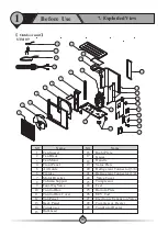
Page 110: ...1 7 Exploded View Before Use 117 Outdoor unit STM 06 ...

Page 111: ...t Four Way Valve Control Box Fan Guard Top Panel Control Box Cover Back Panel Right Plate Gauge Handle Refrigerant Connector 3 8 Refrigerant Connector 1 2 Valve Cover Electronic Expansion Valve Bulkhead Bottom Plate Condensor Compressor Heater Value Plate Condensor Heater 1 1 2 3 4 5 6 7 8 9 10 11 12 13 14 15 16 17 18 19 20 21 22 23 24 25 26 27 28 29 STM 09 18 ...

Page 112: ...ontrol Box Fan motor Air guide 31 32 1 2 3 4 5 6 7 8 9 Top panel Coil and ambient temperature sensor Condensor 10 11 12 22 33 Bulkhead Compressor Handle Suction temperature sensor Bottom plate Valve plate Refrigerant Connector 5 8 Compressor discharge temperature sensor Separator Refrigerant Connector 3 8 Terminal block Crankcase heater PFC transducer EEV controller Condensor heater 4 Way valve El...

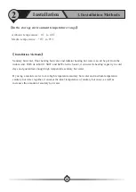
Page 113: ...and guarantees enough high temperature sanitary hot water By using a mixture water to mix high temperature sanitary hot water and medium temperature sanitary hot water together it ensures the ideal temperature of sanitary hot water as well as increases the amount of sanitary hot water 2 1 Installation Methods Installation 120 Ambient temperature to Media temperature to 0 40 0 95 In the storage env...

Page 114: ... in the tank to city water in the coil thus it will have less volume of sanitary hot water available compared with other solutions The advantages of this application is A Heat pump is connected with tank directly so it can effectively ensure the water flow rate inside heat pump system B Sanitary hot water is heated up by going through the coil which makes it unnecessary to have sanitization This w...

Page 115: ...hen 20L W It should be installed between heat pump and distribution system in order to 1 Ensure heat pump unit has stable and enough water flow rate 2 Store heat to minimize fluctuation of system heating cooling load 3 Extend the water volume of distribution system for proper working of heat pump unit If distribution system has enough water volume and can ensure the water flow rate of heat pump sy...

Page 116: ...0 21 22 23 Name Water Outlet Temperature Sensor Hot Water Temperature Sensor 3 way Motorized Valve Water Return Port To Heating Cooling System Drain Port Safety Valve Kit Buffer Tank Mixture Valve 1 0 10V For Circuit 1 Circulation Pump For Distribution Circuit 1 Mixture Valve 2 0 10V For Circuit 2 Circulation Pump For Distribution Circuit 2 Outdoor unit Esterno Interno M1 Drainage High temperature...

Page 117: ...set to OFF 2 1 4 Heating Cooling Circuit 1 Control of Mixing Valve 1 MV1 If system water temperature may higher lower than temperature that are need for circuit 1 in heating cooling operation then a mixing valve can be add to circuit 1 and connected to MV1 port in indoor unit Unit will control the mixing valve mix the supply and return water of circuit 1 to have the temperature read via sensor TV1...

Page 118: ...ng here unit will show relative failure code Tips When Mixing valve is needed In general if system water temperature may higher lower than temperature that are need for this circuit then a mixing valve is needed A If a system has two circuits these two circuits may require different water temperatures Heat pump has to take the higher lower setting among two circuits as the set temperature for heat...

Page 119: ...circulation pump for circuit 1 and P2 circulation pump fo circuit 2 will work once the distribution system has the heating or cooling demand as per the pump setting and obeys following rules Actual temperature in buffer tank detected via Tc 20 in heating Only 20 and above can be useful for distribution system in heating operation Actual temperature in buffer tank detected via Tc in cooling Only 23...

Page 120: ...anitary water tank and have already connected this heater to the heat pump unit so to have it under the control of heat pump City power supply PE N1 L1 N1 L1 PE HWTBH Power Input HWTBH Power Output K2 2 C Outdoor Unit Power Supply 3x2 5mm output Outdoor unit power cable should be connected with these terminals so to get power from indoor unit D Reserved Power Supply 220V 50Hz P 100W E F G Water Pu...

Page 121: ... power supply N2 L2 G AH and HBH Power Input AH and HBH Power Output K1 N2 L2 G 128 Application Side B A G 24VCOM 1 G 24VCOM 2 A B C COM ES COM CS COM HS COM TH D G F E A Communication cable to outdoor unit Please connect A and B together with A and B on outdoor unit B C Motorized mixing valve 1 2 As explained in System illustration chapters this unit can have two water mixture valves for distribu...

Page 122: ...al input external signal should be connected to COOL MODEL SWITCH for cooling operation and HEAT MODE SWITCH for heating operation G High demanding distribution system switch When two heating distribution systems are connected unit should always take the set temperature for high demanding circuit which needs higher temperature in heating and lower temperature in cooling operation as the set temper...

Page 123: ... tightly to ensure it won t get loose Don t connect several parts of cables together to use Make sure the power supply in the local coincide with the power supply marked in rating label Make sure power supply cable and socket can meet the requirement of the input power of the unit 2 Wiring Installation sketch Signal cable between indoor and outdoor unit Power cable between indoor and outdoor unit ...

Page 124: ...l be placed in dry and well ventilated environment F Indoor unit mustn t be installed in an environment where volatile corrosive or flammable liquid or gas exists G During the movement please be careful to keep the unit vertically If the unit is tilted by 30 it may fall down and cause damage to itself or the porter H I Enough space should be left around the indoor unit for further maintenance Don ...

Page 125: ...e condensated water under defrosting mode G Please don t install the indoor and outdoor unit in damp locations otherwise it may cause short circuit or corrosion of some components The unit should be free from corrosive and moisture surrounding Otherwise the lifetime of the unit might be shortened When installing the unit tilt it by 1cm cm to left side of the unit see from front for better water dr...

Page 126: ...n harsh climatic conditions sub zero temperature snow humidity it is recommended to raise the unit off the ground by about 50cm 4 It is recommended to have a base with following size for these units 5 Rubber vibration absorbing mountings are recommended 6 When sitting he unit take care to leave sufficient free space all around it for carrying out maintenance 50cm A If needs to hang the outdoor uni...

Page 127: ... plastic plugs on the pipe sections until the installation of the pipes has begun Precaution Start by drilling with the detection drill to check that there are no obstacles in the way and that the hole on the outside will be correct Holding the detection drill sideways feel inside the wall if there is anything in the way around the detection drill s hole If there is nothing obstructing the detecti...

Page 128: ...d valve B 5 8 gas valve Pipe Routing IMPORTANT Continue the pipe from the indoor unit to the outdoor unit and connect the pipe fittings in the same way The radius at pipe bends must not be less than 15 cm Use a cardboard template to check this Run the power cord along with the pipes Create the bends gradually and carefully You must not bend the pipe straight across for example to the edge of the h...

Page 129: ...36 3 Prepare a vacuum pump and a pressure gauge connect one tube of the pressure gauge to the vacuum pump 4 Connect the other tube of the pressure gauge to the outdoor unit 5 Open pressure gauge and start the vacuum pump to vacuum the unit for around 10 minutes When the pressure gauge shows negative pressure close the pressure gauge and stop vacuuming CAUTION When loosening a connecter always use ...

Page 130: ...of indoor unit to avoid sediments and guarantee water quality City Water Outlet Filter Drain Pipe Connect to Water Tank One Way Valve Ball Way 2 6 Water Pipe Connection Installation After installing the unit please connect the water inlet and outlet pipe according to the local instructions Please carefully select and operate the water pipe After connection the water piping should be pressure teste...

Page 131: ... system of the house 2 7 Installation Of The Kits In The Accessories Installation 138 Kit Ii Sicurezza Collegare ad uno scarico della casa Il kit di sicurezza include una valvola di sicurezza pressione temperatura un degasatore ed un manometro Assicurarsi che questi componenti siano presenti negli accessori 1 Take the four way safety valve kit from accessories 2 Apply sealant tape on threads of th...

Page 132: ...type decorative panel in back side 2 Find 14 screws holes in the picture 2 3 Fix 2pcs long panel on the right and left back side of the unit by fasten the screws and fix 1pcs short panel on the top back side of the unit Please refer the picture 3 and 4 4 It s done Please refer the picture 5 2 1 2 2 Installation 139 3 4 5 2 L type decorative panel in back side 1 long panel L type decorative panel i...

Page 133: ...17 2 The air purging valve discharge the air till water flows out from air purging valve without any air bubble 3 Open ball valve 1 and keep the small cap of air purging valve open and close ball valve 2 Evacuation of floor heating and radiator system 1 Open ball valve 1 2 9 10 11 12 13 14 15 16 and open the small cap of air purging valve 18 to fill water in the whole terminal system 2 If water fl...

Page 134: ...ore start up 2 Pre start up A When the installation of unit is completed water system pipes are well connected and air purging is done no leakage or other problems the unit can be powered to start up B Turn on the unit press the on off button on the operation panel to start the unit Please check carefully if there is some abnormal noise or vibration or the display of wired controller is normal or ...

Page 135: ...han one working mode are activated at the same time corresponding working mode symbol will be shown on the display C Functions 34 7 23 9 6 8 START ENGING STOP 15 26 G Mode E ON OFF H Setting F Touch screen panel A Communication symbol B Working mode C Functions D Warning Heating mode Cooling mode Hot water mode Preheating mode Sleep mode Sanitary hot water storage mode Interruption Defrosting mode...

Page 136: ...hether ambient temperature is lower than 15 It means Unit recover automatically when this coil temperature goes over the safety value again 2 Water Flow Rate Too Small System water flow rate is less than minimum allowable flow rate Check the water system especially the filter check the working status of water pump 3 Water Flow Switch Failure Water flow switch should be in open mode when unit circu...

Page 137: ...l 8 Defrosting Failure 9 System Initialization When unit has just been turned ON this information will be shown It will disappear after system initialization is finished 10 Too Small Water Flow Rate Failure If unit stops due to small water flow rate protection S02 over three times in certain period of time unit 11 Indoor Anti freezing Protection Failure In Cooling If unit stops due to Indoor anti ...

Page 138: ...anitary hot water automatically according to setting Heating Cooling Hot water Auto 34 7 23 9 6 8 15 26 Set mode Current water temperature Set water temperature Ambient temperature Water tank temperature Room temperature START ENGING STOP 34 7 23 9 6 8 15 26 START ENGING STOP 34 7 23 9 6 8 START ENGING STOP 40 35 Set water temperature 145 3 Use 1 Introduction Of Operation Panel ...

Page 139: ... page 65 See page 70 H Setting Press to enter into setting menu See page 71 1 Heating Cooling circuit 1 see page 47 5 Reduced Setpiont for Heating see page 55 See page 71 6 Anti Legionella Function see page 56 7 Vacation Mode see page 57 4 DHW Storage see page 53 8 User Management see page 58 See page 70 2 see page 50 Heating Cooling circuit 2 3 DHW settings see page 51 146 3 Use 1 Introduction Of...

Page 140: ...rts operation again when water temp drops below Tset 1 02 in heating operation or increases over Tset 1 02 in cooling operation Both the set values are based onΔT For example in heating mode if Tset 48 while 1 01 2 and 1 02 1 when the actual water temperature is higher than 50 Tset 1 01 unit stops When unit stops and the actual water temperature drops lower than 47 Tset 1 02 unit will restart Heat...

Page 141: ...ard as possible to get 46 as soon as possible Then compressor will lower its speed If even the compressor works in its lowest allowable speed but actual water temperature still goes over Tset 1 01 unit stops Tset 1 03 T Compressor Speed Reduction 1 04 Set an ideal water temperature for cooling via this parameter 1 05 Heating Curve Function Set whether heating curve function is needed or not If hea...

Page 142: ...this parameter will also be the Room Set Temperature 1 18 Set an ideal room temperature in cooling When in Room Temperature Control mode this parameter will also be the Room Set Temperature For example If 1 16 ON unit works in heating mode If water set temperature in the heating curve is 35 If actual room temperature is 27 while parameter 1 17 Ideal Room Temp in Heating Mode is set to 22 then the ...

Page 143: ...2 2 08 Water Temp C Ambient Temp 3 2 09 Water Temp D Ambient Temp 4 2 10 Water Temp E Ambient Temp 5 Temperature set here is water temperature it is based on the same ambient temperature settings for circuit 1 parameters 1 06 1 10 Temperature settings of the heating operation for circuit 2 VS ambient temperatures Controller create a heating curve for secondary heating system according to these set...

Page 144: ...alue When this function is ON AH Auxiliary Heater or HWTBH Hot Water Tank Back up Heater or both depending on their priority will work individually or together to enhance heat pump s capacity in sanitary hot water mode to heat up the water as soon as possible 3 04 Shifting Priority Starting Temp Set an ambient temperature below which this function starts to work When shifting priority function is ...

Page 145: ...HW and counting the running time The ambient temp Is below 3 04 Whether the unit works in DHW Whether unit works in DHW over 3 05 Whether house heating water temperature drops over 3 07 Whether unit works in Heating over 3 06 The running time for Heating is cleared Unit starts DHW and counting the running time Unit keep on working in Heating and counting the running time Unit works in heating YES ...

Page 146: ...is function 4 02 Sanitary Hot Water Storage Timer Set a working time period for this function and the unit starts to work towards sanitary hot water set temperature in parameter 3 01 within the set time range Different time periods for every day in a week can be set 4 03 Reheating Function Turn ON OFF reheat function 4 04 Reheating Function Timer Set a working time period for reheat function and w...

Page 147: ...n reheating function is activated in the set time period time period set in parameter 4 04 4 06 Reheating Restart T Setting Set reheat restart water T When water temperature drops below T based on reheat set temperature within the set reheating time period unit restarts 154 3 Use 2 Operation Instruction ...

Page 148: ...t temperature during Reduced Setpoint operation 5 03 Timer for Reduced Setpoint Function Set a working time period for Reduced Setpoint Function Different time periods for every day in a week can be set 5 04 Quiet Operation Turn ON OFF Quiet Operation function 5 05 Allowable Temp Drifting Set allowable temperature drift during Quiet Operation When the unit works in quiet mode its output may drop b...

Page 149: ...And Time Set at which time in which weekday s for the start of anti legionella operation 6 03 Setpoint Set the target sanitary hot water temperature for anti legionella Please refer to the local regulation for the correct setting of this temperature 6 04 Duration Set for how long the unit should try to keep this set high temperature to ensure all bacteria in the water tank can be killed 6 05 Finis...

Page 150: ...g Vacation Mode Set a temperature drop for sanitary hot water based on standard DHW set value during the set time period for vacation mode 7 03 Heating Water Temp Drop During Vacation Mode Set a temperature drop for heating based on standard DHW set value during the set time period for vacation mode 7 04 Vacation Start Date Set the date that vacation starts 7 05 Vacation Finish Date Set the date t...

Page 151: ...nged in this menu A password is needed for activating the installer s permission level 8 02 Heating Cooling ON OFF Timer To turn ON OFF the timer function for heating cooling operation 8 03 Heating Cooling ON OFF Timer Set the ON and OFF timer for the heating cooling operation Different time periods for every weekdays in a week can be set 158 3 Use 2 Operation Instruction ...

Page 152: ... control of heating operation also Please place it either inside an ideal position in Hot Water Tank 8 07 Save Current Settings This parameter is used by installer to save the current settings as Installer Settings so the customer can load the saved settings into the system when needed 8 08 Load Saved Settings Loaded the saved Installer Settings 8 09 Reset to Factory Settings Reset the whole syste...

Page 153: ...ion system these setting can only be done under installer level to ensure the safety of the distribution system 9 04 Basic Operation Mode This parameter is used to set the basic operation modes as Water Temperature Control or Room Temperature Control When Basic Operation Mode is activated unit takes room temperature as control object When Basic Operation Mode is not activated unit takes water temp...

Page 154: ...n Note If parameter is set to OFF auto switch function is not activated Then make sure that parameter Heating Water Circuit and Cooling Water Circuit are not set to ON simultaneously as the system can not determine actual requirement due to mode conflict To avoid mode conflict if External Signal Control is used to take control please ensure that the external signal will not be activated at the coo...

Page 155: ...ill not big enough unit will turn on the lower priority Backup Heating Source also 10 03 Backup Heating Source for Sanitary Hot Water Set whether the system has HWTBH Hot Water Tank Back up Heater 10 04 Priority for Backup Heating Sources HWTBH Set the priority of HWTBH compared with unit AH Auxiliary Electric Heater inside the indoor unit When unit works in hot water if heat pump unit can t provi...

Page 156: ...w HWTBH starts If system has HWTBH set via parameter 10 03 and HWTBH has higher priority than AH set via parameter 10 04 Backup Heating for DHW If system has HWT H set via parameter 10 03 and HWTBH has higher priority than AH set via parameter 10 04 When the set and actual water temperature is higher than heat pump maximum allowable water temperature HWTBH works ALONE for DHW while heat pump unit ...

Page 157: ... reaching the set temperature 3 OFF with compressor It means P0 stops after compressor stops 11 4 Pump OFF Interval 11 5 Pump On Time If unit circulation pump P0 working mode is set to Interval working mode that means circulation pump stops after compressor stops but after it stops it will runs for 11 5 minutes after stops for every 11 4 minutes interval time 11 6 Buffer Tank 11 7 P1 for Heating O...

Page 158: ... first stage of Floor Curing operation 12 4 Floor Curing Temperature Setting Stage 2 12 5 Floor Curing Operation Duration Stage 2 Set temperature and lasting time for second stage of Floor Curing operation 12 6 Floor Curing Running Hours 12 7 Highest Water Temp in Floor Curing Operation Three two values are operation data during floor curing operation Unit will take down the operation time and hig...

Page 159: ...13 2 Operation Signal for Electrical Utility Lock Set the type of signal from electricity company Normally Open means when unit can work as normal when it gets ON signal the unit should stop working when it receives a OFF signal Normally Close means the opposite 13 3 HBH During Electrical Utility Lock Set whether turn on HBH Heating Back up Heater when it is blocked by Electrical Utility Lock e g ...

Page 160: ...powered for switching the water flow fully between DHW and Heating Cooling circuit 14 3 Refrigerant Recycle This function can be used by installers to recycle the refrigerant in the complete system into condensing unit for service purpose When it is activated unit will be forced to work in cooling operation for some time to push all refrigerant back to condensing unit 14 4 Control Panel Backlight ...

Page 161: ...ng If water temperature is too low the condenser may have the risk of freezing up and cause damage the complete refrigerant system Thus if water temperature in current working mode is too low for defrosting unit will check the water temperature in other circuit If the water temp in other circuit is good enough for defrosting it will switch the water flow to this circuit for deforsting operation au...

Page 162: ...ry Hot Water Temp TW 07 Cooling Heating Water Temp TC 08 Water Flow Rate 09 Compressor Working Speed 10 EEV Openings 11 Actual Ambient Temp 12 Average Ambient Temp in 1 Hour 13 Average Ambient Temp in 24 Hour 14 High Pressure Pd 15 Low Pressure Ps 16 Discharge Temp Td 17 Suction Temp Ts 18 Outdoor Coil Temp Tp 19 Source Side Water Inlet temperature For Water to Water unit only 20 Source Side Water...

Page 163: ...tem working status Display of Failure Code Record of Previous Failure Display of Failure TW Water temperature for Sanitary hot water tank TC Water temperature for buffer tank TR Room temperature TA Ambient temperature 170 3 Use 2 Operation Instruction ...

Page 164: ...23 9 6 8 START ENGING STOP 15 26 3 Use 2 Operation Instruction This unit has included two electric heaters inside Two electric heaters are used to keep the water temperature when heat pump capacity is not enough or heat pump fail to work as well as heat the water up more rapidly when water temperature is low ...

Page 165: ...h please refer to chapter 10 Backup Heating in page 66 of the manual for more details 2 Actual sanitary hot water temperature is lower than the value set via mechanical thermostat in the unit By doing like this mechanical thermostat works as a limit set manual to ensure electric heater wont be turned ON by heat pump if actual sanitary hot water is over the value set via mechanical thermostat 1 5KW...

Page 166: ...AH according to the priority set via parameter setting 2 Actual heating water temperature is lower than the value set via digital thermostat in the unit By doing like this digital thermostat works as a limit set manual to ensure electric heater won t be turned ON by heat pump if actual water temperature is over the value set via digital thermostat 173 Digital Thermostat Digital Thermostat 1 Press ...

Page 167: ... with power cable or communication cable please connect them separately in order to avoid interference 3 Sensor can t be dip into the hot water for a long time 4 The thermostat initialize the setting the first second after power on so don t touch the button in the first second 5 When the thermostat start to work please remove the film on the display ...

Page 168: ...ck whether fan motor and water pump is working OK whether condenser is blocked whether water temperature too high and whether water inlet outlet temperature has too big difference should no bigger than 8 5 Compressor stops Compressor stops Outdoor 3 Use 175 Ambient temperature is too high or too low for unit to work P11 Compressor shut down due to too high low ambient temperature If system pressur...

Page 169: ...erant that caused this abnormal evaporating pressure whether fan motor and water pump is working OK whether condenser is blocked whether EEV whether EEV works normally whether water temperature too low and whether water inlet outlet temperature has too big difference in cooling should no bigger than 8 Failure 14 Compressor speed down F09 DC fan failure one Speed of DC fan or one of the DC fan for ...

Page 170: ...ter outlet temp sensor failure Check whether unit water outlet temperature sensor is open short circuit or value drifts too much Replace it if necessary Unit stops F17 Unit water inlet temp sensor failure Check whether unit water inlet temperature sensor is open short circuit or value drifts too much Replace it if necessary Unit stops F18 Indoor coil temp sensor failure Check whether indoor temper...

Page 171: ...all water flow rate protection code S02 over three times in certain period of time unit stops and gives S10 failure code It can only be recovered by re powering the unit Check the water system especially the filter check the working statue of water pump Compressor stops S11 Indoor Anti freezing Protection Failure in Cooling If unit stops due to Indoor Anti freezing protection in cooling S01 over t...

Page 172: ...er only needs to clean the surface of the outdoor heat exchanger per month or quarter of a year E If the unit runs in a dirty or oily environment please clean the outdoor heat exchanger and heat exchanger by professionals using specified detergent to ensure the performance and efficiency of the unit F Please pay attention to the ambient environment to check if the unit is installed firmly or if th...

Page 173: ...vice And Maintenance 2 Service 180 Outdoor unit 1 Maintenance of controller b Take off the top cover of the unit see picture a c Take off the electric box cover see picture b d Do necessary maintenance work to the controller of outdoor unit see picture c a Cut off the power supply 4 Top cover Electric box cover a b c Maintenance valve mainly used for vacummizing the system or refrigerant charging ...

Page 174: ...g Failure flickers 0 5s ON 2s OFF 4 JP404 position of jumper for EEPROM programing or refreshing this jumper must be taken out after programing otherwise the unit can t work 5 Connector for software burning tool 6 Dip switch on outdoor PCB 7 8 LED indicator light on outdoor Drive PCB Factory Default Setting in normal operation flickers 2s ON 2s OFF ON OFF Outdoor PCB 2 1 7 8 3 5 4 6 4 2 Service Se...

Page 175: ...ith cables out see picture g h i and j f Put the repaired or new fan motor back and connect all cables back h g j 图i Ground cable Cable connected to PCB Cable connected to fan motor capacitor Take out the motor a Take out the fan blade in same procedure as 4 6 2 b Unscrew the fixture of bottom plate heater see picture a c Disconnect the quick connector for bottom plate heater and take the heater o...

Page 176: ...please clean the heat exchanger as follows A Use a vacuum cleaner to clean the surface of the fins to get rid of the dust or other rubbish B Use a soft nylon brush to clean the fins rinse by water at the same time please don t rinse with high water pressure If the outdoor unit is located in an oily place and is hard to clean please ask for professional service to clean it C After cleaning please l...

Page 177: ...g efficiency F If the refrigerant leaks in indoor environment please ventilate the room G Copper pipe must be used for gas pipe Never use iron pipe aluminium pipe or alloy pipe 4 Service And Maintenance 3 Maintenance 184 Thanks to the normally very high degree of turbulence in the heat exchanger there is a set self cleaning effect in the channels However in some applications the fouling tendency c...

Page 178: ...e water flow 4 Too high water temperature 1 Discharge all refrigerant and charge the unit again with right amount 2 Discharge all refrigerant and charge the unit again with right amount 3 Check the water flow of the system Use a bigger pump to increase the water flow if necessary 4 Check the value of the water temperature sensor to ensure it works properly Too low suction pressure 1 Drier filter i...

Page 179: ... Indoor Unit 5 1 Wiring Diagram Wiring Diagram 186 TAKE CARE This diagram is subject to change with improvement of the unit Always refer to the diagram supplied with the product GB 06 ...

Page 180: ... Indoor Unit 5 1 Wiring Diagram Wiring Diagram 187 GB 09 TAKE CARE This diagram is subject to change with improvement of the unit Always refer to the diagram supplied with the product ...

Page 181: ... Outdoor Unit TAKE CARE This diagram is subject to change with improvement of the unit Always refer to the diagram supplied with the product 5 1 Wiring Diagram Wiring Diagram 188 ...

Page 182: ...lly before use and follow the instructions to operate the unit in order to prevent damages on the device or injuries to staff Specifications are subject to change with product improvements without prior notice Please refer to the specification sticker on the unit for upgraded specifications ...

Reviews: