4
‐
22
Installing
a
new
blade
Step
1
‐
Select
the
most
suitable
saw
blade
for
your
workpiece
considering
the
size,
shape
and
material.
Step
2
‐
Turn
on
the
machine
power
by
switching
to
ON
and
turn
on
the
hydraulic
power.
Step
3
‐
Press
the
saw
bow
up
button
and
elevate
the
saw
bow
until
the
right
insert
holder
is
clear
of
the
front
fixed
vise.
Step
4
‐
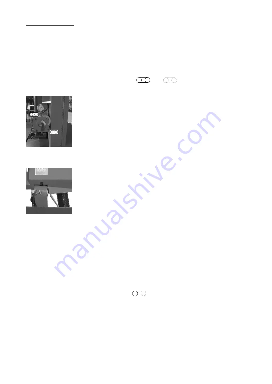
Turn
the
tension
controller
handle
from
“
”
to
“
”
position
to
release
tension.
The
idle
wheel
will
then
move
slightly
toward
the
direction
of
the
drive
wheel.
Step
5
‐
Open
the
idle
and
drive
wheel
cover.
Step
6
‐
Loosen
the
wire
brush
assembly
lock
lever
and
move
the
wire
brush
away
from
the
blade.
Step
7
‐
Unclamp
the
left
and
right
carbide
inserts.
Pull
down
the
saw
blade
from
the
carbide
inserts,
wire
brush
assembly
and
from
the
two
wheels.
Step
8
‐
If
necessary,
clean
the
carbide
inserts
before
installing
a
new
saw
blade.
Step
9
‐
Place
the
new
blade
around
the
idle
wheel
and
the
drive
wheel
Step
10
‐
Insert
the
blade
into
the
left
and
right
tungsten
carbide
inserts.
The
back
and
the
sides
of
the
blade
need
to
be
touching
the
inserts
as
well
as
the
adjacent
rollers.
Step
11
‐
Place
the
blade
to
the
drive
wheel
and
press
the
back
of
the
blade
against
the
flange
of
the
drive
wheel.
Step
12
‐
Make
sure
the
back
of
the
blade
is
also
pressed
against
the
flange
of
the
idle
wheel.
Step
13
‐
Turn
the
tension
controller
handle
to
[
]
position
to
obtain
blade
tension.
Step
14
‐
Make
sure
the
sides
of
the
blade
are
in
close
contact
with
the
carbide
inserts
and
then
tighten
the
left
and
right
carbide
inserts.
Step
15
‐
Gently
close
the
idle
and
drive
wheel
covers.
Step
16
‐
Press
the
saw
blade
start
button
to
start
the
blade.
Allow
the
blade
to
run
for
a
few
rotations
then
press
the
saw
bow
up
button
to
elevate
the
saw
bow.
Open
the
wheel
covers
and
make
sure
the
blade
has
not
fallen
off
the
drive
and
idle
wheels.
If
the
blade
has
shifted,
follow
the
same
procedure
to
reinstall
the
blade
again.
Summary of Contents for SH-7550S
Page 2: ......
Page 8: ......
Page 17: ...1 9 Illustration Safety Labels ...
Page 22: ...2 4 FLOOR PLAN Machine top view ...
Page 23: ...2 5 Machine front view ...
Page 24: ...2 6 Machine side view ...
Page 34: ......
Page 64: ...5 2 1000525 張 鴻 昌 ...
Page 65: ...5 3 1000525 張 鴻 昌 ...
Page 66: ...5 4 1000525 張 鴻 昌 ...
Page 67: ...5 5 1000525 張 鴻 昌 ...
Page 68: ...5 6 ...
Page 69: ...5 7 ...
Page 70: ...5 8 ...
Page 71: ...5 9 ...
Page 72: ......
Page 73: ...6 1 Section 6 HYDRAULIC SYSTEM HYDRAULIC CIRCUIT DIAGRAM ...
Page 74: ...6 2 ...
Page 80: ......
Page 114: ......
Page 116: ......
Page 117: ......


