


27
28
29
30
32
33
34
35
36
38
39
40
41
1
2
3
4
5
6
7
8
9
24
10
11
37
12
13
14
15
16
17
25
19
18
20
23
21
26
22
NO.
PA
RT NO.
PA
RT NAME
PA
RT NAME
(CH)
Q'TY
1
AHA
-0
701
B
Left fix
ed
insert
左
固
固
定
鋼
鋼
1
1/4
1
2
AHA
-0
70
2B
Left movable insert
左
活
活
定
鋼
鋼
1
1/4
1
3
AHA
-0
704A
Press
ure bloc
k
下
油
座
(E
U7
9
用
)
2
4
AHA
-0
70
7B
Roller pin
導
帶
軸
1
1/4
2
5
AHA
-0
70
7C
Roller pin
導
帶
軸
(
三
)
2
6
AHA
-0
708B
Washer
導
帶
墊
墊
1
1/4
2
7
AHA
-0
709
Left fittin
g
左
彈
活
1
8
AHA
-0
71
0
Spring
定
鋼
鋼
彈
彈
2
9
AHA
-0
711
Adjusti
ng
bolt
左
調
機
蓋
絲
1
10
AHA
-0
71
3-
1
Straight sh
aft
軸
軸
座
固
固
軸
2
11
AHA
-0
719
Spacer
導
帶
座
墊
鋼
1
12
AHA
-0
73
7
Saw arm fix
ed block
上
鋸
固
固
塊
2
13
AHA
-0
741
Right fitti
ng
右
彈
活
1
14
AHA
-0
742
Right in
sert k
nob
右
調
機
蓋
絲
1
15
AHA
-0
743
B
Right movable insert
右
活
活
定
鋼
鋼
1
1/4
1
16
AHA
-0
744B
Right fixe
d insert
右
固
固
定
鋼
鋼
1
1/4
1
17
AHA
-0
745
Coolant noz
zle
冷
冷
水
水
油
1
18
C250H-3
021
Adjusti
ng
Bolt
滑
濺
調
機
蓋
絲
1
19
C250H-31
01
Saw arm sliding board
上
鋸
滑
濺
1
20
C250H-31
03
Left g
uide
arm
左
上
鋸
1
21
C250H-31
05
Right
guide arm
右
上
鋸
1
22
C250H-31
11
Nam
eplate
右
上
鋸
滑
座
座
牌
1
23
C250H-31
12
Nam
eplate
左
上
鋸
滑
座
座
牌
1
24
C250H-31
31
Left insert hold
er
左
導
帶
座
1
25
C250H-3161
Right
guide roll
er seat
右
導
帶
座
1
26
C250H-316
7
Position pin
導
帶
座
固
定
銷
1
27
PA
A-
10
-1
2
Set scre
w
止
止
蓋
絲
(
公
)
1
28
PA
A-6
-8
Set scre
w
止
止
蓋
絲
(
公
)
1
29
PBA
-1
2-40
Bolt
有
接
內
內
角
蓋
絲
(
公
)
1
30
PBA
-5-8
Bolt
有
接
內
內
角
蓋
絲
(
公
)
1
31*
PBA
-6-1
2
Bolt
有
接
內
內
角
蓋
絲
(
公
)
1
32
PBA
-6-
20
Bolt
有
接
內
內
角
蓋
絲
(
公
)
1
33
PL
A-
12
-55
Bolt
外
內
角
接
蓋
絲
(
公
)
1
34
PO
A-
10
Nut
蓋
螺
(
公
)
4
35
PO
A-
12
Nut
蓋
螺
(
公
)
1
36
PP
-142
70
Bearing
軸
軸
4
37
PP
-52111
E
Saw arm handl
e
上
鋸
把
把
1
38
PPA
-1
0
Washer
平
油
華
華
(
公
)
1
39
PPA
-1
2
Washer
平
油
華
華
(
公
)
1
40
PQA
-1
0
Spring
washer
彈
彈
華
華
(
公
)
5
41
PQA
-1
2
Spring
washer
彈
彈
華
華
(
公
)
4
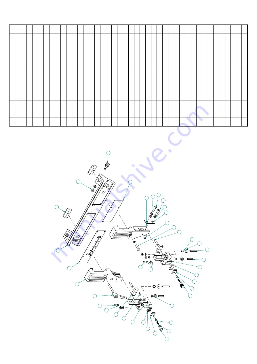
Gu
id
e Arm A
ssembly
10-12
Summary of Contents for C-260NC
Page 2: ......
Page 4: ......
Page 10: ......
Page 14: ...1 4 Illustration Safety Fence Safety Fence Safety Fence...
Page 16: ...1 6 Illustration Emergency Stop Emergency Stop Button...
Page 18: ...1 8 Illustration Safety Labels...
Page 20: ......
Page 25: ...2 5 FLOOR PLAN Machine top view Machine side view...
Page 26: ......
Page 36: ......
Page 66: ......
Page 68: ...5 2...
Page 69: ...5 3...
Page 70: ...5 4...
Page 71: ...5 5...
Page 72: ...5 6...
Page 73: ...5 7...
Page 74: ...5 8...
Page 75: ...5 9...
Page 76: ......
Page 78: ...6 2...
Page 79: ...6 3...
Page 81: ...22 12 12 12 12 8 16 19 20 6 16 21 13 1 3 5 9 6 5...
Page 83: ...6 7...
Page 84: ...6 8...
Page 86: ...5 12 12 12 12 8 15 18 19 6 15 20 13 1 3 21 8 9 6 10...
Page 88: ......
Page 92: ......
Page 115: ...1 HHGLQJ HG VVHPEO 10 7...
Page 122: ...C 260NC C 320GNC C 325NC 10 14...
Page 123: ...10 15 Front Top Clamp...
Page 125: ...10 17 Rear Top Clamp...
Page 128: ......
Page 130: ......
Page 131: ......


