326142000
1
GENERAL INFORMATION
IMPORTANT: To the user of this manual - This manual is a guide for installing, operating, and
maintaining this equipment. Refer to Table of Contents for page location of information pertaining to
questions that arise during installation, operation, service and maintenance, or troubleshooting this
equipment.
GENERAL DESCRIPTION
This section gives the description, theory of operation, and design data for the FCB Solid-State Post-Mix
Two-Flavor Dispenser with Hot-Gas Defrost (hereafter referred to as a Unit).
UNIT DESCRIPTION
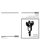
The Unit (see Figure NO TAG) consists basically of two freeze cylinders each containing an internal beater
driven by an electric motor, one refrigeration system with a 2-horsepower compressor, one carbonator which
feeds both carbonator-blender tanks, a timer-controlled automatic hot-gas defrost system to defrost the freeze
cylinders, and interconnecting tubing, components, and fittings necessary to regulate, transfer, and dispense
product. The components are attached to a steel frame and are enclosed in a steel cabinet. The cabinet panels
are easily removed to facilitate installation and service and maintenance. A transparent faceplate, with an
integral relief valve and a removable self-closing dispensing valve, is mounted on front of each freeze cylinder.
A removable drip tray, with cup rest, is located directly below the dispensing valves.
CAUTION: Before shipping, storing, or relocating Unit, syrup systems must be sanitized
and all sanitizing solution must be purged from syrup systems. All water must also be
purged from plain and carbonated water systems. A freezing ambient environment will
cause residual sanitizing solution or water remaining inside Unit to freeze resulting in damage to
internal components.
FIGURE 1. FCB (SOLID-STATE) POST-MIX TWO-FLAVOR DISPENSER
Table 1. Design Data
Table 2. Design Data
Part Number:
Part Number:
60 Hz Unit
416120XXX
416120XXX
50 Hz Unit
496120XXX
Summary of Contents for 326142000
Page 23: ...16 326142000 THIS PAGE LEFT BLANK INTENTIONALLY ...
Page 33: ...26 326142000 THIS PAGE LEFT BLANK INTENTIONALLY ...
Page 37: ...30 326142000 FIGURE 5 OPERATING CONTROLS ...
Page 38: ...31 326142000 FIGURE 6 UNIT INTERNAL COMPONENTS ...
Page 59: ...52 326142000 FIGURE 12 WATER STRAINER SCREEN AND DOUBLE LIQUID CHECK VALVE ...
Page 66: ...59 326142000 FIGURE 16 REFRIGERATION FLOW DIAGRAM ...
Page 67: ...60 326142000 FIGURE 17 WIRING DIRGRAM ...
Page 77: ...326142000 70 4 5 6 7 8 11 12 14 15 79 84 85 87 88 115 117 118 4 FIGURE 20 FCB FLOW DIAGRAM ...
Page 86: ...79 326142000 THIS PAGE LEFT BLANK INTENTIONALLY ...