


Revision
04
February 19, 1998
363-765-104-04
28
PairGain
Engineering - Plant Series
FRE-765
List
4x
Auxiliary Power Pairs.
When PG-Flex is used with a doubler, follow the instructions for the appropriate
FRE-765 enclosure.
For the FRE-765 Lists 4, 4A, 4B, 4D, 4E, and 4F install the two AMP Quiet Front terminations (kit part number
150-1399-25) and wire for the doubler as follows (the kit provides white and blue jumper wires):
1
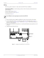
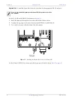
Install the two AMP Quiet Front terminations into the FRE-765 (see
):
a
Connect a white jumper wire to PWR_1_T (J10A) and a blue jumper wire to PWR_1_R (J11A) wire-
wrap pins.
b
Connect a white jumper wire to PWR_2_T (J12A) and a blue jumper wire to PWR_2_R (J13A) wire-
wrap pins.
c
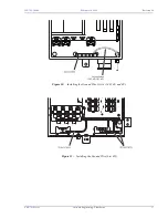
Loosen the Phillips-head screw for each connector and slide the bracket on the AMP Quiet Front
termination under it.
d
Tighten the Phillips-head screw.
e
Insert and tighten the white and blue jumper wires into the AMP Quiet Front terminations.
Figure 19.
Installing Power Pair Terminations
2
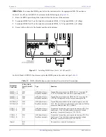
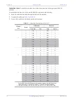
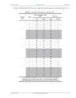
For List 4, 4A, 4B, and 4F only, route the auxiliary power pairs:
a
Route the auxiliary power pairs from the CO shelf to AMP Quiet Front terminations through the strain
relief on the bottom of the enclosure. Use a cable tie to secure to the bracket near the cable entrance.
b
Terminate the power pairs on the AMP Quiet Front terminations per
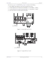
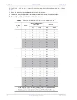
3
For List 4D and 4E, connect the auxiliary power pairs per
.


