


Revision
04
February 19, 1998
363-765-104-04
16
PairGain
Engineering - Plant Series
FRE-765
List
4x
Wiring
The following section describes how to connect and verify the FRE-765 cable installations.
Chassis Ground Wiring.
To install the chassis ground wire, follow the instructions below and refer to the
specific illustrations:
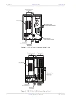
For Lists 4, 4B and 4G refer to
.
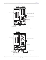
For Lists 4A, 4D, 4E and 4F refer to
For List 4H refer to
1
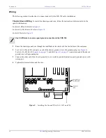
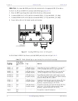
Route the chassis ground wire through the small hole in the strain relief on the bottom of the enclosure.
2
For Lists 4, 4B, and 4G, connect one end of the chassis ground wire to the grounding lug (see
).
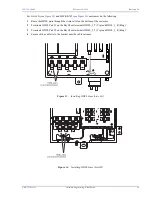
For Lists 4A, 4D, 4E, 4F (
), and 4H (
) connect one end of the chassis
ground wire to the grounding bar.
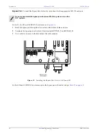
3
Connect the other end of the chassis ground wire to a suitable ground termination point (ground rod or cold
water pipe).
4
Tighten the strain relief around the wire.
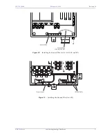
Figure 9.
Installing the Ground Wire (List 4, 4B, and 4G)
Use 6 AWG wire to ensure a good ground connection to the FRE-765.


