


12
Make all the 485 Buss connections in a “daisy chain” configuration as shown.
Power up the domes and the DVRs.
Establish the protocol and Baud rate being used by the system RS485 Buss to control
the speed domes. (see 485/232 details in the System Settings menu of the DVR).
Note: They must all be set to use the same.
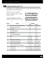
Set the protocol and baud rate of the keyboard to be the same as rest of the system
using the Dil switches on the rear of the Keyboard (refer to page 4 for settings).
Set the PTZ ID’s of each dome camera connected. (refer to Camera setting: PTZ in the
Engineer Manual). Each camera must have a unique ID.
e.g.
DVR 1 = Camera 1: PTZ ID 011, Camera 2: PTZ ID 012 etc.
DVR 2 = Camera 1: PTZ ID 021, Camera 2: PTZ ID 022 etc.
DVR 3 = Camera 1: PTZ ID 031, Camera 2: PTZ ID 032 etc.
DVR 4 = Camera 1: PTZ ID 041, Camera 2: PTZ ID 042 etc.
Assign each DVR with a unique ID. e.g. ID 101, ID 102, ID 103 etc. (see page 5).
Switch on the power to the Keyboard.
The Keyboards will initialise then default to providing PTZ control.
Current CamID:001
PELCO_D 2400bps
Display:
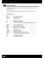
The keyboard can now be used to control and operate any of the connected speed
domes. (see page 19 for details).
Press the Function button F3 on the Keyboard and the operating Mode for that
Keyboard will change to provide Symphony DVR control.
Addr: 00001
* DVR-SHE *
Display:
Enter the ID of any one of the DVRs you wish to access (see page 12 for details)
Summary of Contents for Symphony
Page 1: ...1 SYMPHONY KEYBOARD ...