16
30. Unscrew spring retainer 613060 and remove spring 613058, ball 844077 and push rod 613264, for inspection.
REASSEMBLY
General
The tool should be reassembled in the reverse order of disassembly.
As all of the various gears and bearings are being assembled, they should be coated with a generous amount of "LUBRIPLATE
#907" grease.
After power unit is reassembled, place a few drops of 10W machine oil in the hose before attaching the air hose. This will insure
immediate lubrication of all motor parts as soon as the air is applied.
During reassembly, be sure that the drive coupling hex and spline are engaged in the power unit and drill head respectively.
Adjustment of retract lever must be done after tool is fully assembled. When the lever is pushed down into feed cycle it should
stay there until the stop collar engages the lever and tool goes into retract.
Right Angle Drill Head
When reinstalling pinion and shaft and bearing into cover, the idler gear must be slipped onto the idler gear shaft simultaneously. Refer
to steps 13,14 and 15 in Disassembly.
Gear Case
When reinstalling the front bearing 843615, in the gear case, the shield on the bearing must be facing out. Refer to step 21 in Disassembly.
Gear Stop Adjustment
In order to make the adjustment, there are two methods that can be used. The preferred method is to make the adjustment during
assembly of drill before the retract body and its’ related components are attached to the angle head. With the 622985 gear
stop in position with and the 622984 clutch rollers positioned on top of the cam lobes, rather than in the detents, the 867502
set screws are turned clockwise until the springs just begin to make up solid, but are not crushed or distorted. The screws are
then rotated counterclockwise 45° minimum to 90° By using this method, it’s easier to determine when the spring makes up
solid so that there is tendency to force the screw in too deep and damage the springs.
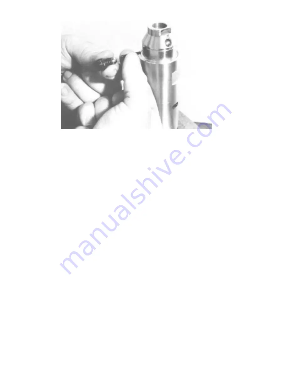
If the adjustment is to be performed with the drill fully assembled, the clutch rollers will normally be resting in the detents. The
screws are then rotated in the clockwise direction until the springs just begin to go solid. Care must be used so as not to distort
the springs. Once the solid state is achieved, the set screws are backed out (counterclockwise) one full turn plus the 45° to 90°.


