


6
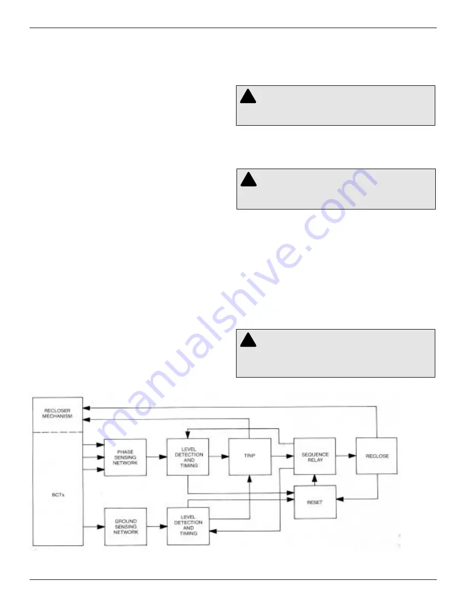
Figure 6.
Functional block diagram of Type ME control.
Type ME Electronic Recloser Control
A functional block diagram of the control operation is shown
in Figure 6. Line current conditions are continuously monitored
by the three bushing-type current transformers in the recloser.
output from these transformers is fed to the trip network in the
control, which includes: the minimum-trip resistors, isolation
transformers, and rectifier circuits.
If current remains above the minimum-trip level, the tripping
—reclosing sequence of fast and delayed operations is repeat-
ed as programmed to lockout.
When current above the selected minimum-trip level is
detected in one or more phases, the following chain of events
will occur for an operating sequence of two-fast and two-
delayed operations:
The overcurrent signal is integrated with time on the charac-
teristic curve of the timing plug in Socket 1 to produce the sig-
nal which energizes the trip circuit. Energizing the trip circuit
connects the battery to the trip solenoid, tripping the recloser.
Simultaneously, the sequence relay advances to energize the
first reclosing interval-delay plug. Upon expiration of this
reclosing interval delay, a closing signal, from the control, clos-
es the recloser, and the sequence relay sets up the circuitry for
the second fast trip operation.
If the overcurrent is cleared before the operating sequence
reaches lockout, the reset-delay circuit starts timing when the
recloser closes into the unfaulted line. When the reset-delay
plug times out, the sequence relay is reset to the start or
“HOME” position and the control is ready for another two-fast,
two-delayed trip-operating sequence. However, should the
fault restart before the reset plug times out, the control will
continue its operating sequence, where it left off last, and the
reset-delay timing will be erased.
Ground-fault sensing and tripping operations occur exactly
the same as phase-fault sensing and tripping, except that
zero-sequence (ground) current is sensed instead of phase
current. The ground-fault circuitry includes its own minimum-
trip resistor, fast and delayed trip-timing plugs, and number of
fast operations setting. Reclose and reset intervals and opera-
tions to lockout are common for both phase-trip and ground-
trip modes of operation.
PERlODIC FIELD INSPECTlON
AND MAINTENANCE
Periodic inspection of the ME control should include these proce-
dures:
1. Remove control from service (if connected to an in service
recloser):
A. Switch Ground Trip Block switch to “BLOCK”.
B. Disconnect control cable from control.
2. Check the outer surface of the control cabinet for paint
scratches. Touch up any paint scratches to maintain the cabi-
net condition.
3. If the second entrance hole in the bottom of the cabinet is not
used, be sure that the hole plug is secure in the bottom of the
housing to maintain its weatherproof design.
4. Inspect the gasketing. Check the control interior for any mois-
ture or foreign matter. Repair or correct if necessary.
5. Check that the timing plugs, reset and reclosing interval
delays, and minimum-trip resistors are firmly in their sockets
(Figure 2).
6. Swing open the front panel. Check to see that all leads to tie-
board terminals are secure (Figure 7).
CAUTION:
Shorting battery positive to battery
negative at the battery test terminals will cause per-
manent damage to the control. The control will be inoper-
ative and possible misoperation (unintentional operation)
of the recloser may result.
!
CAUTION:
In order to prevent possible, misoper-
ation (unintentional operation) of the recloser, the
control must be removed from service prior to performing
any maintenance, testing or programming changes.
!
WARNING:
High voltage. Contact with high volt-
age will cause serious personal injury or death.
Follow all locally approved safety procedures when work-
ing around high voltage lines and equipment.
!
Summary of Contents for Kyle Type ME Series
Page 43: ...Figure 54 continued Form 2 Connections continued 43 S280 75 2...
Page 45: ...Figure 55 continued Form 3 Connections continued 45 S280 75 2...
Page 47: ...Figure 56 continued 47 S280 75 2 Form 3 Connections continued...
Page 49: ...Figure 57 continued Form 3A Connections continued S280 75 2 49...