background image

Wired Remote Controller XK19                                                

14

1

6

8

9

10

7

3

4

5

2

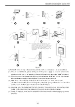
Fig.15

Fig.15 shows the installation steps of the wired remote controller, but there are some issues that need your attention.

(1). Prior to the installation, please firstly cut off the  power supply of the wire  buried in the 

installation hole, that is, no operation is allowed with electricity during the whole installation.

(2). Pull out the four-core twisted pair line from the installation holes and then let it go through 

the rectangular hole behind the soleplate of the wired remote controller.

(3). Stick the soleplate of wired controller on the wall and then use screw M4×25 to fix
      soleplate and installation hole on wall together, attach the sponge 20×20×2 at the screw hole 
      and then press it with fingers to make sure it’s attached firmly.
(4). Insert the four-core twisted pair line into the slot of the wired remote controller and then 

buckle the front panel and the soleplate of the wired remote controller together.

(5). 

ST2.9X6.

Note

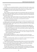
CN1 is 485 communication interface and it used 

           for connecting the 4-core communication wire. 

           These two needle stands(CN2

CN3) are used for 

           connecting the smart zone controller. There is no 

           sequence for these two needle stands. You can 

           connect one or two needle stand(s) basing on the 

           requirement.

Summary of Contents for XK19

Page 1: ...g our product Please read this Owner s Manual carefully before operation and retain it for future reference If you have lost the Owner s Manual please contact the local agent or visit www cooperandhunter com Owners s manual Wired Remote Controller XK19 and Wireless Remote Controller YT1F ...

Page 2: ...ectly under the sunlight Never beat throw and frequently disassemble the wired remote controller and the wireless remote controller Never operate the wired remote controller and the wireless remote controller with wet hands Please read the manual carefully before using and installing this product ...

Page 3: ... 4 Fan Setting 5 3 5 Timer Setting 5 3 6 Swing Setting 7 3 7 Sleep Setting 8 3 8 Turbo Setting 9 3 9 E heater Setting 10 3 10 Blow Setting 11 3 11 Other Functions 12 4 Installation and Dismantlement 13 4 1 Connection of the Signal Line of the Wired Remote Controller 13 4 2 Installation of the Wired Remote Controller 13 4 3 Dismantlement of the Wired Remote Controller 16 5 Errors Display 16 Ⅱ Wirel...

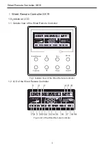
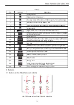
Page 4: ...e Function Timer On Off SHIELD MEMORY MASTER SAVE BLOW QUIET CO2 AUTO TURBO SET HOUR F E HEATER A U T O Fig 1 Outside View of the Wired Remote Controller 1 2 LCD of the Wired Remote Controller SHIELD MEMORY MASTER SAVE BLOW QUIET CO2 AUTOT URBO SET HOUR F E HEATER A U T O 1 2 3 4 5 6 7 8 9 10 12 11 13 14 15 16 17 18 19 Fig 2 LCD of the Wired Remote Controller ...

Page 5: ...s the original setting state after power failure and then power recovery 11 Master wired remote controller this function is yet unavailable for this unit 12 It blinks under on state of the unit without operation of any button 13 Energy saving function this function is yet unavailable for this unit 14 Ambient preset temperature value 15 Electric auxiliary heating function 16 Blow function 17 Timing...

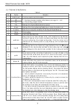
Page 6: ...epress them for 5s to quit this state 4 6 Mode Under OFF state the Celsius and Fahrenheit scales can be switched by pressing Mode and for five seconds 5 7 Function Timer Under OFF state it is available to go to the commissioning status by pressing Function and Timer for five seconds and let 00 displayed on the temperature display area by pressing Mode then adjust the options which is shown on the ...

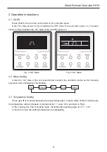
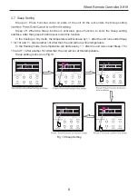
Page 7: ...tate Fig 5 On State 3 2 Mode Setting Under the On state of the unit press Mode to switch the operation modes as the following sequence Auto Cooling Dry Fan Heating Auto Cooling Dry Fan Heating 3 3 Temperature Setting Press or to increase decrease the preset temperature If press either of them continuously the temperature will be increased or decreased by 1 every 0 5s as shown in Fig 6 In the Cooli...

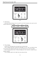
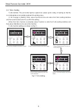
Page 8: ...Cancel Fan Mode Function Timer On Off AUTO Fig 7 3 5 Timer Setting Under the On Off state of the unit press Timer to set timer off on Timer on setting press Timer and then LCD will display xx x hour with hour blinking In this Timer off setting press Timer if LCD won t display xx x hour and then it means the timer setting is canceled Timer off setting under the On state of the unit is shown as Fig ...

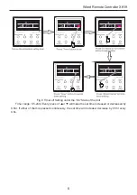
Page 9: ...W 6 Fig 8 Timer off Setting under the On State of the Unit Timer range 0 5 24hr Every press of or will make the set time increased or decreased by 0 5hr If either of them is pressed continuously the set time will increase decrease by 0 5hr every 0 5s ...

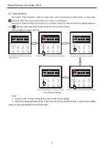
Page 10: ...en the Swing function is on press Function to enter the Swing setting interface with blinking After that press Enter Cancel to cancel this function Swing setting is shown as Fig 9 Fig 9 Swing Setting Note Sleep Turbo or Blow setting is the same as the Swing setting After the setting has been done it has to press the key Enter Cancel to back to the setting ...

Page 11: ...face After that press Enter Cancel to can this function In the Cooling or Dry mode the temperature will increase by 1 after the unit runs under Sleep 1 for 1hr and 1 after another 1hr After that the unit will run at this temperature In the Heating mode the temperature will decrease by 1 after the unit runs under Sleep 1 for 1hr and 1 after another 1hr After that the unit will run at this temperatu...

Page 12: ...emperature can quickly approach the setting value In the Cooling or Heating mode press Function till the unit enters the Turbo setting interface When the Turbo function is activated press Function to enter the Turbo setting interface and then press Enter Cancel to cancel this function Turbo function setting is as shown in Fig 11 Fig 11 Turbo Setting ...

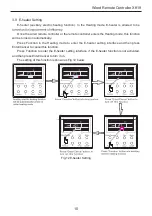
Page 13: ...oller enters the Heating mode this function will be turned on automatically Press Function in the Heating mode to enter the E heater setting interface and then press Enter Cancel to cancel this function Press Function to enter the E heater setting interface if the E heater function is not activated and then press Enter Cancel to turn it on The setting of this function is shown as Fig 12 below Fig ...

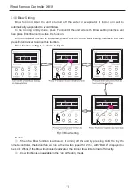
Page 14: ...he Blow function is activated press Function to the Blow setting interface and then press Enter Cancel to cancel this function Blow function setting is as shown in Fig 13 Fig 13 Blow Setting Notes When the Blow function is activated if turning off the unit by pressing On Off or by the remote controller the indoor fan will run at the low fan speed for 2 min with BLOW displayed on the LCD While if t...

Page 15: ...nt temperature is the sensed at the wired controller 02 in the timer display area Select the temperature sensor at the return air inlet under the cooling dry and fan modes while select the temperature sensor at the wired controller under the heating and auto modes 03 in the timer display area Select the temperature sensor at the wired controller under the cooling dry and fan modes and select the t...

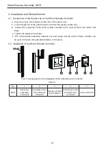
Page 16: ... 4 pin socket of the indoor unit PCB Tighten the signal wire with ties The communication distance between the main board and the wired remote controller can be up to 20 meters the standard distance is 8 meters 4 2 Installation of the Wired Remote Controller 1 PVC Pipe 3 4 5 2 Fig 14 Accessories for the Installation of the Wired Remote Controller Table 3 No 1 2 3 4 5 Name Socket box embedded in the...

Page 17: ...troller 3 Stick the soleplate of wired controller on the wall and then use screw M4 25 to fix soleplate and installation hole on wall together attach the sponge 20 20 2 at the screw hole and then press it with fingers to make sure it s attached firmly 4 Insert the four core twisted pair line into the slot of the wired remote controller and then buckle the front panel and the soleplate of the wired...

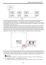
Page 18: ...t to the n wired controller Except the last wired controller in the control system only use CN2 or CN3 and the other one will not be connected there s no the sequence and the importance for the wired controller The series number in the figure is only for the sake of clarity Fig 17 shows schematic diagram of DIP switch There is a 2 bit DIP switch on the main board of wired controller XK19 As for th...

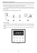
Page 19: ... lines of the wired remote controller must be the shielding twisted pair lines 4 3 Dismantlement of the Wired Remote Controller 1 3 4 2 5 Errors Display If there is an error occurring during the operation of the system the error code will be displayed on the LCD as show in Fig 18 If multi errors occur at the same time their codes will be displayed circularly Note In event of any error please turn ...

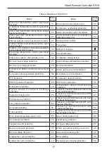
Page 20: ...le unit over current protection E5 Compressor demagnetization protection HE Over phase current protection P5 PFC protection Hc Compressor desynchronizing H7 IPM Temperature Protection P8 IPM Current protection H5 Over power protection L9 Compressor phase loss reversal protection Ld System charge shortage or blockage protection F0 Frequency restricted reduced with whole unit current protection F8 C...

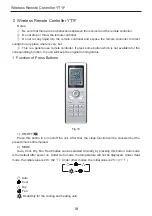
Page 21: ...hich is not available for the corresponding function the unit will keep the original running status 1 Function of Press Buttons Fig 19 1 ON OFF Press this button to turn on off the unit After that the sleep function will be canceled but the preset time is still remained 2 MODE Auto Cool Dry Fan Heat modes can be selected circularly by pressing this button Auto mode is the default after power on Un...

Page 22: ...it is the Timer value 6 LIGHT Light On and Light Off can be set by pressing this button when the unit is at On or Off status After powered on the default is Light On 7 TURBO In Cool or Heat mode pressing this button can activate or deactivate this function When this function is on its symbol will be displayed Any change of either mode or fan speed will make this function canceled automatically 8 X...

Page 23: ...e the time increased or decreased by 1 minute If the button is pressed down for more than 2 seconds the time will be changed quickly in Once Timer ON has been set already it can be canceled by repressing it Before the setting please adjust the CLOCK to the current actual time 15 TIMER OFF TIME OFF can be activated by pressing this button with OFF blinking The method of setting is the same as that ...

Page 24: ...n off the unit the whole unit will be stopped completely b About AFTERHEAT X FAN Under the Heat mode or Auto Heat mode if the unit is turned off the compressor and outdoor fan will stop running immediately and the upper and lower guide board will rotate to the horizontal position while the indoor fan will still run at the low fan speed Then 10 seconds later the unit will stop completely c About AU...

Page 25: ...Cooper Hunter International Corporation www cooperandhunter com ...

Reviews: