User Interface
CoolMaster User Manual
15
www.coolautomation.com
© 2008 Cool Automation
User Interface
5
LCD Screen Explanation
5.1
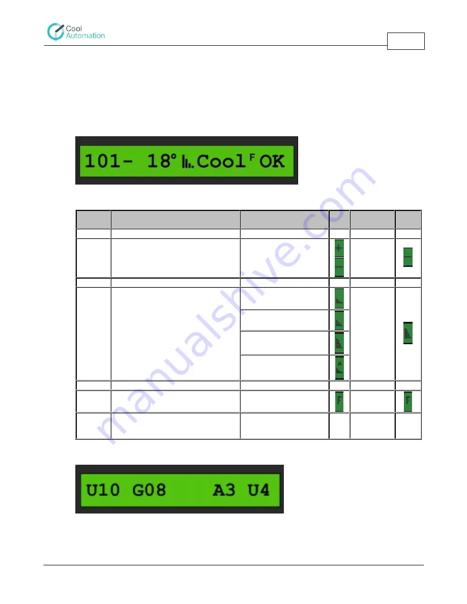
Two types of screens can appear on the LCD of the CoolMaster. One screen shows the indoor units
status, as shown in the figure and the explanation table below.
The following table describes what is shown on the LCD Display of the CoolMaster.
Segment
Number
Description
Range
Example
1
Address of the indoor unit
100 - 815
101
2
Operation Status
"+" - off,
"-" - on
"-"
3
Set Point Temperature
16 - 32
"18"
4
Fan Speed
Low
high
Medium
High
Auto
5
Operation Mode
Cool Heat Fan Dry
"Cool"
6
Filter Sign
7
Error Status
OK - Normal Opearation
U4 - example of
malfunction
Ok
Another screen shows the number of identified indoor units and number of groups
U – Number of recognized indoor units (in the example above – 10)
G – Number of groups (in the example above – 8)
A3 U4 – current malfunction codes in the system


