COOK SQN Series Installation, Operation And Maintenance Manual Download Page 8

8

SQN IO&M

B51141-004

Bearing Replacement

The fan bearings are pillow block ball bearings. 

1.  Loosen screws on bearing cover.

2.  Push bearing cover toward the wheel. As the bearing 

cover moves toward the wheel it will slide down to re-

veal the bearings and shaft. 

3.  Remove the old bearing.

4.  Remove any burrs from the shaft by sanding.

5.  Slide new bearings onto the shaft to the desired lo-

cation and loosely mount bearings onto the bearing 

support. Bearing bolts and setscrews should be loose 

enough to allow shaft positioning.

6.  Correctly position the wheel and tighten the bearing 

bolts securely to the bearing support.

7.  Align setscrews bearing to bearing and secure tightly 

to the shaft.

NOTICE! Never tighten both pairs of setscrews before 

securing bearing mounting bolts. This may damage 

the shaft.

8.  Inspect the wheel position again. If necessary, read-

just by loosening the bearing bolts and setscrews and 

repeat from step 5.

Wheel Replacement

1. 

Drill two 1/4” diameter holes, 180° apart centered ap

-

proximately between the shaft and the outside diam-

eter of the hub, 3/8” to 1/2” in depth.

2. 

Tap 1/4” holes to 5/16” thread with a 5/16” hole tap. Do 

not drill or tap greater than recommended. 

3.  Screw the puller arms to the full depth of the threads 

into the tapped holes. Align center of the puller with 

the center of the shaft. Ensure all setscrews in the 

hub, normally two, are fully removed.

4.  Slowly remove wheel from the shaft. 

Recommended Puller

Lisle No. 45000 Sterling Wheel Puller. This puller is 

available at most automotive parts retail outlets.

Wheel Replacement Components

Drilled hole placement.

Wheel puller.

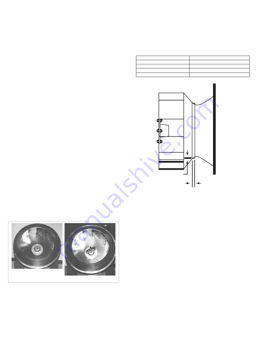
Wheel-to-Inlet Clearance

The correct wheel-to-inlet clearance is critical to prop-

er fan performance. This clearance should be verified be

-

fore initial start-up since rough handling during shipment 

could cause a shift in fan components. Refer to 

Wheel/

Inlet

 drawing for correct overlap.

Adjust the overlap by loosening the wheel hub and mov-

ing the wheel along the shaft to obtain the correct value.

A uniform radial gap (space between the edge of the 

cone and the edge of the inlet) is obtained by loosening the 

inlet cone bolts and repositioning the inlet cone.

Wheel/Inlet Overlap

Size

Maximum Overlap

100- 195

5/8”

210-270

3/4”

300-445

1”

490 730

1-1/4”

Radial Clearance

Overlap

Summary of Contents for SQN Series

Page 1: ...milling will cause hazardous conditions due to unexpected rotation of components Impellers should be blocked in position or air passages blocked to prevent draft when working on fans Friction and powe...

Page 2: ...torage If the fan is stored for any length of time prior to installa tion completely fill the bearings with grease or moisture inhibiting oil Refer to Lubricants on page 5 Also store the fan in its or...

Page 3: ...o Blower Installation Belt tension is determined by the sound the belts make when the fan is first started Belts will produce a loud squeal which dissipates after the fan is operating at full capacity...

Page 4: ...correct number of side dis charge duct connection collars are provided 4 steel flang es for a single side discharge and 8 for dual To install the side discharge duct connection collar re move the appr...

Page 5: ...Refer to Recommended Torque chart 2 Inspect belt wear and alignment Replace worn belts with new belts and adjust alignment as needed Refer to Belt and Pulley Installation 3 Bearings should be inspecte...

Page 6: ...de Access Side Access Side Access Side Access Side Access Side Access Side Access Bottom Access Side Access Example 1 Example 2 Example 3 Example 4 Example 5 Example 6 Example 7 Example 8 Example 9 Ex...

Page 7: ...le grease such as Exxon Mobil Polyrex EM and Chevron SRI Motor Services Should the motor prove defective within a one year pe riod contact your local Loren Cook representative or your nearest authoriz...

Page 8: ...e diam eter of the hub 3 8 to 1 2 in depth 2 Tap 1 4 holes to 5 16 thread with a 5 16 hole tap Do not drill or tap greater than recommended 3 Screw the puller arms to the full depth of the threads int...

Page 9: ...P 1 2 3 4 5 6 7 8 9 10 11 12 13 14 15 Airflow 16 17 18 Part No Description Sizes 60 165 Sizes 180 210 Sizes 225 402 1 L Bolt 2 L Bolt 2 L Bolt 2 2 Motor Plate 1 Motor Plate 1 Motor Plate 1 3 Motor 1 M...

Page 10: ...1 Bearing Support Reinforcement Plate 2 9 Belt Cover 1 Belt Cover 1 Belt Cover 1 10 Bearing Support Assembly 1 Bearing Support Assembly 1 Bearing Support Assembly 1 11 Inlet Panel 1 Inlet Panel 1 Inl...

Page 11: ...Rail 2 2 Inlet Panel 1 3 Inlet Cone Sizes 135 165 1 4 Housing Frame Support 6 5 Housing Panel Motor Side 1 6 Access Panel 3 7 Motor Cover Back Plate 1 8 Cooling Tube 2 9 Electrical Box 10 Electrical C...

Page 12: ...his warranty does not cover defects resulting from normal wear and tear To make a warranty claim notify Loren Cook Company General Offices 2015 East Dale Street Springfield Missouri 65803 4637 explain...

Reviews: