COOK SQN Series Installation, Operation And Maintenance Manual Download Page 4

4

SQN IO&M

B51141-004

Blower Installation

The fan is shipped with the motor in the 12 o’clock posi-

tion and the feet are shipped loose. (Feet may be under 

weather cover) 

1.  Upon receipt of the fan, remove the eight (8) feet 

shipped with the fan and ensure the feet are the cor-

rect type. Refer to 

Figure 4

.

2.  Determine how the fan is to be mounted. Refer to 

Foot 

Mounting Illustrations

.

3. 

Remove the 5/16” bolt(s) from the corner of the hous

-

ing in which the foot is to be attached. 

4.  Place the foot over the open bolt hole(s) and bolt the 

foot to the unit. Refer to 

Figure 4

.

Foot Mounting Illustrations

Sizes 70 - 135

Sizes 150 - 225

Sizes 245 - 402

View of A or E Foot Assembly

Not on direct drive

(A)


Not on direct drive

(B)

Not on direct drive

(C)


Not on direct drive

(D)

Not on direct drive

(E)

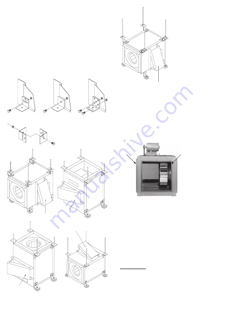
SQN Optional Side Discharge Installation

Upon receiving an SQN for a side discharge installation, 

please note that the rear discharge block-off panel is in

-

stalled on the unit and that the correct number of side dis-

charge duct connection collars are provided (4 steel flang

-

es for a single side discharge and 8 for dual). 

To install the side discharge duct connection collar, re-

move the appropriate access door. Install the side dis-

charge duct connection collar using the bolts that were re-

moved with the access door. Then connect the duct work. 

See page 6 for examples.

Rear discharge

block off planel

Side Discharge Duct

Connection Collar

NOTICE! Original Loren Cook Company labels must 

remain with the unit. This may require swapping ac-

cess doors from one side to the other.

Final Installation Steps

1.  Ensure that all accessories are installed.

2.  Ensure that the blower is secured to ductwork.

3.  Inspect wheel-to-inlet clearance. Ensure wheel does 

not rub against the inlet.

4.  Test the fan to ensure the rotation of the wheel is the 

same as indicated by the rotation label.

5.  Inspect for correct amperage with an ammeter and 

correct voltage with a voltmeter.

Operation

Pre-Start Checks

1.  Lock out all the primary and secondary power sources.

2.  Inspect and tighten fasteners and setscrews, partic-

ularly fan mounting and bearing fasteners. Refer to 

Figure 4

Summary of Contents for SQN Series

Page 1: ...milling will cause hazardous conditions due to unexpected rotation of components Impellers should be blocked in position or air passages blocked to prevent draft when working on fans Friction and powe...

Page 2: ...torage If the fan is stored for any length of time prior to installa tion completely fill the bearings with grease or moisture inhibiting oil Refer to Lubricants on page 5 Also store the fan in its or...

Page 3: ...o Blower Installation Belt tension is determined by the sound the belts make when the fan is first started Belts will produce a loud squeal which dissipates after the fan is operating at full capacity...

Page 4: ...correct number of side dis charge duct connection collars are provided 4 steel flang es for a single side discharge and 8 for dual To install the side discharge duct connection collar re move the appr...

Page 5: ...Refer to Recommended Torque chart 2 Inspect belt wear and alignment Replace worn belts with new belts and adjust alignment as needed Refer to Belt and Pulley Installation 3 Bearings should be inspecte...

Page 6: ...de Access Side Access Side Access Side Access Side Access Side Access Side Access Bottom Access Side Access Example 1 Example 2 Example 3 Example 4 Example 5 Example 6 Example 7 Example 8 Example 9 Ex...

Page 7: ...le grease such as Exxon Mobil Polyrex EM and Chevron SRI Motor Services Should the motor prove defective within a one year pe riod contact your local Loren Cook representative or your nearest authoriz...

Page 8: ...e diam eter of the hub 3 8 to 1 2 in depth 2 Tap 1 4 holes to 5 16 thread with a 5 16 hole tap Do not drill or tap greater than recommended 3 Screw the puller arms to the full depth of the threads int...

Page 9: ...P 1 2 3 4 5 6 7 8 9 10 11 12 13 14 15 Airflow 16 17 18 Part No Description Sizes 60 165 Sizes 180 210 Sizes 225 402 1 L Bolt 2 L Bolt 2 L Bolt 2 2 Motor Plate 1 Motor Plate 1 Motor Plate 1 3 Motor 1 M...

Page 10: ...1 Bearing Support Reinforcement Plate 2 9 Belt Cover 1 Belt Cover 1 Belt Cover 1 10 Bearing Support Assembly 1 Bearing Support Assembly 1 Bearing Support Assembly 1 11 Inlet Panel 1 Inlet Panel 1 Inl...

Page 11: ...Rail 2 2 Inlet Panel 1 3 Inlet Cone Sizes 135 165 1 4 Housing Frame Support 6 5 Housing Panel Motor Side 1 6 Access Panel 3 7 Motor Cover Back Plate 1 8 Cooling Tube 2 9 Electrical Box 10 Electrical C...

Page 12: ...his warranty does not cover defects resulting from normal wear and tear To make a warranty claim notify Loren Cook Company General Offices 2015 East Dale Street Springfield Missouri 65803 4637 explain...

Reviews: