6
HMD IO&M
B51242-002
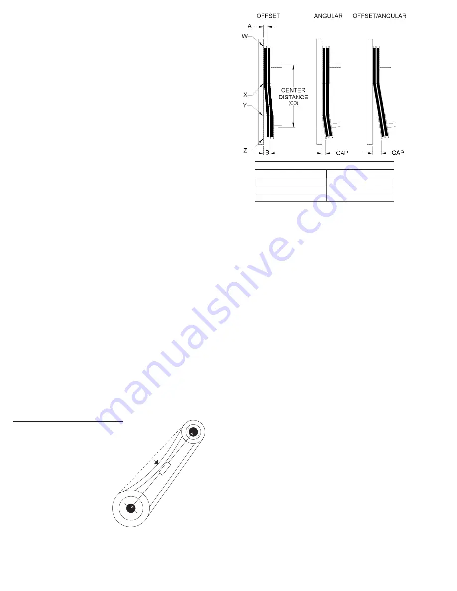
Tolerance
Center Distance
Maximum Gap
Up thru 12”
1/16”
12” up through 48
1/8”
Over 48”
1/4”
NOTICE! Premature or frequent belt failures can
be caused by improper belt tension, or misaligned
sheaves. Abnormally high belt tension or drive mis-
alignment will cause excessive bearing loads and
may result in failure of the fan and/or motor bearings.
Abnormally low belt tension will cause squealing on
start-up, excessive belt flutter, slippage, and overheat
-
ed sheaves.
1. V-belt drives must be checked on a regular basis for
wear, tension, alignment, and dirt accumulation.
2.
Check the tension by measuring the deflection in the
belt as shown here.
3. Check the alignment by using a straight edge across
both sheaves. The drawings below show where to
measure the allowable gap for the drive alignment
tolerance. All contact points (indicated by WXYZ) are
to have a gap less than the tolerance shown in the
table. When the pulleys are not the same width, the
allowable gap must be adjusted by half of the differ
-
ence in width.
Snow Accumulation
Clear snow away from roof mounted units. Keep the
snow clear of the intake and access doors.
Motors
Motor maintenance is generally limited to cleaning and
lubrication (where applicable). Cleaning should be limited
to exterior surfaces only. Removing dust and grease build-
up on the motor assures proper motor cooling.
Motors supplied with grease fittings should be greased
in accordance with the manufacturer’s recommendations.
Greasing motors is only intended when fittings are provid
-
ed. Many motors are permanently lubricated, requiring no
additional lubrication.
NOTICE! Do not allow water or solvents to enter the
motor or bearings. Motors and bearings should never
be sprayed with steam, water or solvents.
3. With all access panels in place, the fan running and
discharging 70ºF (21ºC) air, connect a U-Tube ma-
nometer to the outer sensing probes and measure
the static pressure across the burner. The proper
static pressure should be (check
CFM / Static Pres-
sure chart
on page tk). If needed, evenly adjust the
baffles, keeping the burner centered in the opening
until the required pressure is obtained. The pressure
drop was set at the factory and may not need adjust-
ment. When required pressure is obtained, be sure
to reconnect the outer sensing probes. This process
may need to be repeated until the proper pressure is
achieved. This adjustment will change the air quanti-
ty delivered by the unit and therefore the air quantity
delivered should be rechecked. Refer to the
Blower
Start-Up
section.
• To increase static pressure decrease the opening.
• To decrease static pressure increase the opening.
4. Monitor the unit’s actual temperature rise by placing
a thermocouple in the unit’s inlet and a second in the
discharge, three duct diameters downstream of the
burner. Send the unit to maximum flame by chang
-
ing the rotation of the motor pack from left to right.
Use a screw driver on top of modular gas valve.
While monitoring the unit’s temperature rise, set the
maximum firing rate by adjusting the regulator until
the designed temperature rise is achieved. After set-
ting the maximum firing rate, reconnect the wire to
the amplifier. Do not set the burner maximum firing
rate based on gas pressure. It should be set based
on the unit’s designed temperature rise shown on
the label. Setting the maximum firing rate during
mild weather conditions may cause the high limit to
trip out during extreme conditions requiring manual
resetting. Gas trains are equipped with a combined
regulator valve. Clockwise rotation increases the
temperature rise; counterclockwise rotation de-
creases the temperature rise. The minimum setting
for the maximum firing rate may be higher than re
-
quired. This is acceptable, the burner will modulate
as needed. To convert from Natural Gas to LP or
vice versa follow the instructions associated with the
high fire gas valve.
5. Set the operating temperature.
Maintenance - All year
V-Belt Drives
NOTICE! Do not pry belts on or off
the sheave. Loosen belt tension
until belts can be removed by
simply lifting the belts off
the sheaves. When replac-
ing V-belts on multiple
groove drives, all belts
should be changed to
provide uniform drive
loading. Do not install
new belts on worn
sheaves. If the sheaves have grooves worn in them,
they must be replaced before new belts are installed.
1 foot
1/4 inch


