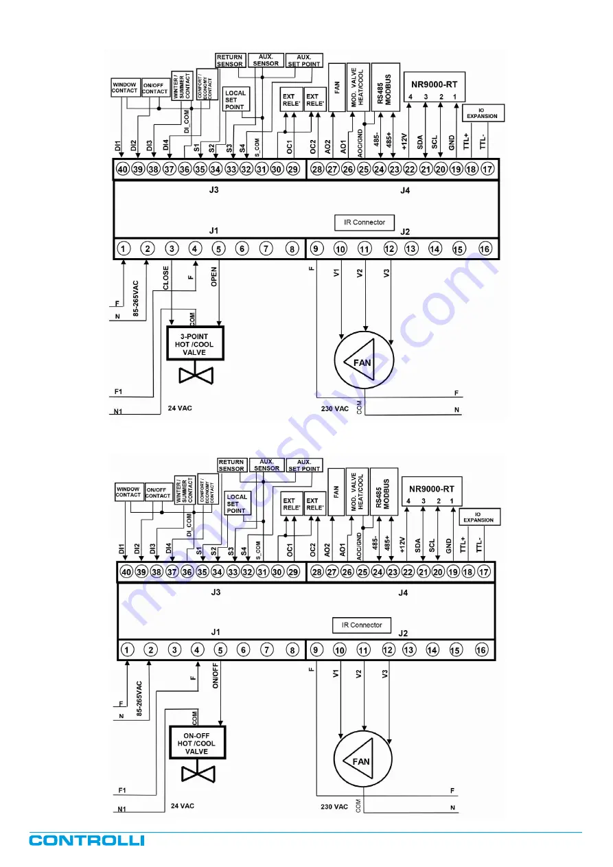
Example of 2-pipe plant with 24V 3-point valves
Example of 2-pipe plant with 24V ON/OFF valves
1
st
Issue rev. c
12/2015
DBL408e
Page 7
Page 1: ...elector Remote Power off or Comfort Economy digital inputs can be used to interface the controller with a Presence Detector to mini mize costs for heating and cooling When digital inputs are in use they have priority on remote sensor and supervisory system Sensors with a sensing element NTC10K Ohm 25 C Accuracy 1K β 25 C 3435 reference Controlli room sensors S4xxA B and SNTC xL Digital inputs can ...
Page 2: ...mm2 cross section wires for J3 and J4 To use wire terminals on power supply wires follow the instructions in order to prevent accidental contacts between cables at different voltages in case of wrong installation The main power is fully isolated but we suggest to install a protection device compliant to existing national rules with a 125mA intervention threshold and a minimum 3mm contact opening T...
Page 3: ...al 4 24Vac Comfort economy contact 36 DI_COM input digital COM COM 35 S1 input analogue input Return sensor 34 S2 input analogue input Remote set 33 S3 input analogue input Auxiliary Loop Return Sensor 32 S4 input analogue input Remote Set Auxiliary Loop 31 S_COM input COM COM 30 OCC output COM Open Collector 12V Com Open Collector 12V 29 OC1 output Open Collector 1 Open Collector for external REL...
Page 4: ...WIRING DIAGRAMS Example of 4 pipe plant with 230V 3 point valves Example of 4 pipe plants with 230V ON OFF valves 1st Issue rev c 12 2015 DBL408e Page 4 ...
Page 5: ...Example of 4 pipe plants with 24V 3 point valves Example of 4 pipe plant with 24V ON OFF valves 1st Issue rev c 12 2015 DBL408e Page 5 ...
Page 6: ...Example of 2 pipe plant with 230V 3 point valves Example of 2 pipe plant with 230V ON OFF valves 1st Issue rev c 12 2015 DBL408e Page 6 ...
Page 7: ...Example of 2 pipe plant with 24V 3 point valves Example of 2 pipe plant with 24V ON OFF valves 1st Issue rev c 12 2015 DBL408e Page 7 ...
Page 8: ...et point and the fan speed all other parameters can be modified only through the su pervisory system or the dedicated configuration tool The controller can operate also without the Remote Sensor using a dedicated an alogue input Return Sensor The controller will consider the data acquired by the Sensor and by the Supervisory system if present and will perform a P or PI or PID regulation to drive t...
Page 9: ... economy mode will be increased with the set correction during sum mer and decreased during winter This information can be defined through a dedicated digital input or via parameter and it can be set by the supervisory system or by a configuration tool using MODBUS protocol N B by default Summer Winter changeover is set by local mode in plants equipped with a supervisory system it has to be precon...
Page 10: ...1 speed fan Operation Diagram 4 5 3 point Valves and 1 speed fan Operation Diagram 5 6 ON OFF Valves and Modulating FAN 0 10V Operation Dia gram 6 7a 2 pipe plant Proportional Valve 0 10V and Modulating Fan 0 10V Operation Diagram 7a 7b 4 pipe plant Sequence Valves 0 5 6 10V and Modulating Fan 0 10V Operation Diagram 7b In case of use of 3 speed fans 3 relays the 0 10V outputs are always available...
Page 11: ... aside 4 ON OFF valves and 1 Speed FAN The valves are activated in ON OFF mode with hysteresis Speed 1 follows to the Proportion al Band as shown in the diagram aside 5 3 point valves and 1 Speed FAN The valves are activated in Pro portional mode 0 100 using a proportional band Speed 1 follows to the Proportion al Band as shown in the diagram aside 1st Issue rev c 12 2015 DBL408e Page 11 ...
Page 12: ... the Proportion al Band as shown in the diagram aside generating a 0 10V output control signal Control modes diagrams 2 pipe plant Out AO1 Out AO2 6 No Fan 6 Yes Fan 7 Yes Hot cool valve Fan 7 No Hot cool sequence Fan Modulating valve and or fan application example 7b 0 5 6 10 V Sequence Valves and Proportional Speed Fan 0 10V 4 pipe plant The valves are activated in Pro portional mode 0 100 using...
Page 13: ...ory Setting default address1 ON OFF OFF OFF 1 OFF ON OFF OFF 2 ON ON OFF OFF 3 OFF OFF ON OFF 4 ON OFF ON OFF 5 OFF ON ON OFF 6 ON ON ON OFF 7 OFF OFF OFF ON 8 ON OFF OFF ON 9 OFF ON OFF ON 10 ON ON OFF ON 11 OFF OFF ON ON 12 ON OFF ON ON 13 OFF ON ON ON 14 ON ON ON ON Controller used as IO expansion DIP5 DIP6 DIP7 CONFIGURATION DIAGRAM OFF OFF OFF ON OFF Valves and 3 FAN speed factory setting ON ...
Page 14: ...on Time Hot loop 1 min 30 min 5 min Integration Time Cool loop 1 min 30 min 5 min Cut Off Function with Extra stroke of 33 0 1 1 ENABLE Summer Winter Changeover 0 1 0 WINTER Operation Mode COMFORT 0 Economy 1 Frost 2 0 2 0 COMFORT Delay Time Fan Start 0 255 0 DISABLE Delay Time Fan Stop 0 255 0 DISABLE minimum fan speed 0 50 0 DISABLE Controller Modbus Address 1 250 1 Operation Diagram 1 7 2 2 4 P...
Page 15: ...tact Disable digital input DI1 Enable digital input DI1 0 5 Temperature Set Correction Mode 10 35 C 3K 0 6 DIP switch Enable Disable 0 7 Electrical Battery Disable Enable 0 STATUS WORD parameter NR9000 RT Value Default 0 Display Off 1 Display Only Room Temperature in page 0 2 Display Only Temperature Set in page 0 3 Display Room Temperature in page 0 with T Set Fan e Mode fixed 4 Display Room Temp...
Page 16: ...case the controller does not allow the user to change all the function listed above and the remote terminal can show and send to controller only the room temperature It is possible to calibrate the room temperature displayed on the re mote sensor of 3 C label tAr and to read and set the MODBUS ad dress label Add of the controller connected to the sensor following these instructions press button 4 ...
Page 17: ...s Press SELECT button to stop the set up Press ON SEND button to send information to the unit TIMER PROGRAM Start time Press SELECT button twice the word PROGRAM and the word START lighting will be displayed Press or button the word START will become fix and the hours value will start lighting Use button to increase or to decrease the hours Press SELECT button the minutes value will light Use butt...
Page 18: ... connected to NR9000 controller and a double side tape for fixing on smooth surfaces In case the flat cable is not connected to the receiver proceed as follows 1 unscrew the two screws on the receiver to open the back cov er a 6 terminal connector will be visible 2 insert one end of the cable inside the connector The connector can be mounted in one direction only as it is polarized 3 close again t...