Continental Fireplaces BCDV2CFN Installation And Operating Instruction Download Page 47

47

W415-0680 / 04.10.08

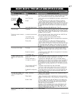
BCDV36CFG TROUBLE SHOOTING GUIDE

B

EFORE


ATTEMPTING


TO


TROUBLESHOOT

PURGE


YOUR


UNIT


AND


INITIALLY


LIGHT


THE


PILOT


AND


THE


MAIN


BURNER


WITH


THE


GLASS


DOOR


REMOVED

.

SYMPTOM

PROBLEM

TEST SOLUTION

Pilot will not light

Wiring

- Verify the "S" wire for the sensor and the "I" wire for the ignitor are connected 
to the correct terminals (not reverse) on the module and pilot assembly.

Makes noise with 
no spark at 
pilot burner

Loose Connection

- Verify no loose connections, electrical shorts in the wiring or ground out to any 
metal object.

Module

- Turn the ON/OFF switch to the "OFF" position. Remove the igniter wire 
"I" from the module. Place the ON/OFF switch to the "ON" position. Hold a 
grounded wire about 3/16" away from the "I" terminal on the module. If no spark 
the "I" terminal module must be replaced. If there is a spark the "I" terminal is 
fi ne. Inspect pilot assembly for a shorted wire or cracked insulator around the 
electrode.

Ignitor spark gap is incorrect

- Spark gap of the ignitor to the pilot should be .17" tor 1/8"

Pilot will not light.

Transformer

- Verify the transformer is installed and plugged into the module. Check voltage 
of the transformer under load at the spade connections on the module with the 
ON/OFF switch in the "ON" position. Acceptable readings of a good transformer 
are between 3.2 and 2.8 volts A.C.

Makes no noise with no spark at 
pilot burner

A shorted or loose connection

- Remove and reinstall the wiring harness that plugs into the module. Remove 
and verify continuity of each wire in wiring harness.

Improper switch wiring

- Troubleshoot the system with the simplest ON/OFF switch

Module is not grounded

- Verify the value and pilot assemblies are properly grounded to the metal chas-
sis of the fi replace or log set.

Faulty module

- Turn the ON/OFF switch to the "OFF" position. Remove the igniter wire 
"I" from the module. Place the ON/OFF switch to the "ON" position. Hold a 
grounded wire about 3/16" away from the "I" terminal on the module. If no spark 
the "I" terminal module must be replaced. If there is a spark the "I" terminal is 
fi ne. Inspect pilot assembly for a shorted wire or cracked insulator around the 
electrode. 

Pilot sparks but will not light

Gas supply

- Verify that the incoming gas line ball valve is "Open". Verify that the inlet 
pressure reading is within acceptable limits, inlet pressures must not exceed 
14" W.C.

Module is not grounded

- Verify the value and pilot assemblies are properly grounded to the metal chas-
sis of the fi replace or log set.

Out of propane gas.

- Fill the tank.

Continues to sparks and pilot 
lights, but main burner will not 
light

Short or loose connection in 
sensor rod

- Verify all connections. Verify the connections from the pilot assembly are tight; 
also verify these connections are not grounding out to any metal. 

Poor fl ame rectifi cation or 
contaminated   sensor rod

- Verify the fl ame is engulfi ng the sensor rod. This will increase the fl ame 
rectifi cation. Verify correct pilot orifi ce is installed and inlet gas specifi cations to 
manual. (Remember, the fl ame carries the rectifi cation current, not the gas. If 
the fl ame lifts from pilot hood, the circuit is broken. A wrong orifi ce or too high 
of an inlet pressure can cause the pilot fl ame to lift.) The sensor rod may need 
cleaning.

Poor grounding between pilot 
assembly and gas valve

- Verify that the wire harness is fi rmly connected to module.

- Verify that the ceramic insulator around the sensor rod is not cracked, dam-
aged, or loose. Verify the connection from the sensor rod to the sensor wire.

Damaged pilot or dirty sensor 
rod

- Clean sensor rod with an emery cloth to remove any contamination that may 
have accumulated on the sensor rod. Verify continuity with multimeter with 
ohms set at the lowest range.

Pilot lights Stops sparking / pilot 
remains lit but burner will not 
turn on

Wiring / Connection

- Inspect all wires, ensure good tight connections. Verify that all wiring is 
installed exactly as specifi ed.

Wiring harness

- Inspect the wiring harness, and verify the harness is tightly connected to 
the module. Verify that you have 7 wires and they are connected in the right 
order.

Module or Valve

- Conduct the following test to verify if the problem is the module or valve. 
To measure voltages, turn multimeter to "DC" place the red lead from mul-
timeter on the screw on the terminal block for the wire you are checking, 
touch black lead to ground (valve body).

Importantly, a "Zero" volts reading does not automatically indicate a bad 
module, there may be too little resistance in the valve solenoid. Check 
the Green wire disconnected from valve that the voltage output from the 
module should be between 2 and 3 volts

Exhaust fumes smelled in room, 
headaches.

Fireplace is spilling.

- Check all seals.

Summary of Contents for BCDV2CFN

Page 1: ...1 W415 0680 04 10 08 10 00 W415 0680 04 10 08...

Page 2: ...arances Optional Clean Face Surround Installation BCDV36CF G only Finished Floor Installation Hearth Installation NOTE CHANGES OTHER THAN EDITORIAL ARE DENOTED BY A VERTICAL LINE IN THE TABLE OF CONTE...

Page 3: ...President s Limited Lifetime Warranty WOLF STEEL LTD may at its discretion fully discharge all obligations with respect to this warranty by refunding to the original warranted purchaser the wholesale...

Page 4: ...tions with BCDV36CF G are common to both the BCDV36CF and the BCDV36CFG FOR YOUR SATISFACTION THIS FIREPLACE HAS BEEN TEST FIRED TO ASSURE ITS OPERATION AND QUALITY BCDV36CF G Maximum input for the BC...

Page 5: ...AL INLET LEFT SIDE 41 1 2 37 35 1 2 GAS INLET FIGURE 5 INSTALLATION OVERVIEW FIGURE 7 See the section MINIMUM MANTEL AND ENCLOSURE CLEARANCES Side Wall See the section INSTALLATION FRAMING See the sec...

Page 6: ...htemperaturesilicone RTV This same sealant may be used on both the inner exhaust and outer intake vent pipe joints of all other approved vent systems except for the exhaust vent pipe connection to the...

Page 7: ...7 W415 0680 04 10 08 FIGURE 8...

Page 8: ...For optimum performance it is recommended that all horizontal runs have a 1 rise per foot When terminating vertically the vertical rise is a minimum 3 feet and a maximum 40 feet from the centre of th...

Page 9: ...he 45 offset In this case zero rise is acceptable when using rigid See FIGURE 18 Flexible venting must maintain a 6 rise See FIGURE 19 PERISCOPE TERMINATION CORNER TERMINATION BCDV36CF G BCDV42CF PERI...

Page 10: ...n Horizon tal run vertical rise to maximum of 40 feet Horizontal run verti cal rise to maximum of 24 75 feet 4 2 times the verti cal rise equal to or greater than the horizontal run Vertical rise is e...

Page 11: ...ET HT The shaded area within the lines represents acceptable values for HT and VT for the following symbols used in the venting calculations and examples are greater than equal to or greater than less...

Page 12: ...TICAL RISE IN INCHES VT HORIZONTAL VENT RUN PLUS OFFSET IN FEET HT The shaded area within the lines represents acceptable values for HT and VT when HT VT Simple venting con guration only one 90 elbow...

Page 13: ...9 ft V2 6 ft VT V1 V2 9 6 15 ft H1 3 ft H2 2 ft H3 1 5 ft HR H1 H2 H3 3 2 1 5 6 5 ft HO 03 four 90 elbows 90 03 90 90 90 90 90 8 1 ft HT HR HO 6 5 8 1 14 6 ft HT VT 14 6 15 29 6 ft Formula 1 HT VT 14...

Page 14: ...19 25 Since both formulas are met this vent con guration is acceptable For vent con gurations requiring more than two 90 elbows the following formulas apply H1 H2 H3 H4 V1 V2 90 90 45 90 90 FIGURE 28...

Page 15: ...g con guration only two 90 elbows FIGURE 29 V1 5 ft V2 10 ft VT V1 V2 5 10 15 ft H1 3 ft H2 2 5 ft HR H1 H2 3 2 5 5 5 ft HO 03 three 90 elbows 90 03 90 90 90 90 5 4 ft HT HR HO 5 5 5 4 10 9 ft HT VT 1...

Page 16: ...this vent con guration is unacceptable H1 H2 V3 V1 90 90 90 V2 90 when HT VT Simple venting con gurations See graph to determine the required vertical rise VT for the required horizontal run HT FIGURE...

Page 17: ...Example 1 45 90 H1 H2 V1 FIGURE 35 V1 8 ft VT V1 8 ft H1 2 5 ft H2 2 ft HR H1 H2 2 5 2 4 5 ft HO 03 one 45 elbows two 90 elbows 135 03 225 135 2 7 ft HT HR HO 4 5 2 7 7 2 ft HT VT 7 2 8 15 2 ft Formul...

Page 18: ...ing con gurations 45 MAXIMUM VERTICAL RISE IN FEET VT HORIZONTAL VENT RUN PLUS OFFSET IN FEET HT The shaded area within the lines represents acceptable values for HT and VT For vent con gurations requ...

Page 19: ...ow three 90 elbows 135 03 45 90 90 90 135 5 4 ft HT HR HO 8 5 4 13 4 ft HT VT 13 4 2 5 15 9 ft Formula 1 HT VT 3VT 3 x 2 5 7 5 ft 13 4 7 5 Since this formula is not met this vent con guration is unacc...

Page 20: ...unit Press rmly on the cap while securing to ensure an airtight seal Do not damage the gasket FAILURE TO INSTALL THE CAP WILL CAUSE THE FIREPLACE TO FUNCTION IMPROP ERLY AND CAN CAUSE INJURY OR PROPER...

Page 21: ...f 2 all around the vent pipe on all horizontal runs to combustibles is required Use restop spacer W010 1778 supplied VERTICAL VENT SECTIONS A minimum of 1 all around the vent pipe on all vertical runs...

Page 22: ...p only on the 7 outer vent pipe ELBOW SPACER For safe and proper operation of the replace follow the venting instructions exactly All inner exhaust and outer intake vent pipe joints may be sealed usin...

Page 23: ...lustrated The vent system must be supported approximately every 3 feet for both vertical and horizontal runs Use noncombustible strapping to maintain a clearance to combustibles of 1 VERTICAL AIR TERM...

Page 24: ...eelventpipecollar orequivalentloosely onto the air terminal assembly as it is passed through the attic The air terminal must be located vertically and plumb 6 Remove nails from the shingles above and...

Page 25: ...2 strand solid core millivolt wire through the electrical hole located at the bottom left side of the unit The recommended maximum lead length depends on wire size WIRE SIZE MAX LENGTH 14 gauge 100 f...

Page 26: ...replace edge Enclosure top 8 1 4 to top of replace Recessed depth 17 1 4 Sides and bottom of the vent pipe 1 Top of vent pipe 2 Ceiling 72 from bottom of unit BCDV36CF G See alternate clearances on p...

Page 27: ...ensure that clearance to combustibles is maintained within the cavity Combustible materials may be installed ush with the front of the replace but must not cover any of the black face areas of the rep...

Page 28: ...TLE THIS AREA MUST REMAIN EXPOSED TO ALLOW FOR PROPER DOOR REMOVAL 12 TO COMBUSTIBLE MANTLE The finishing material can be installed below the top opening a maximum of 1 1 2 Enough clearance to the doo...

Page 29: ...1 2 of cement board and steel header supplied with surround kit or non combustible equiva lent must be used on the top only of the front face See Figure 80 See Venting Section FIGURE 79 FIGURE 81 NOTE...

Page 30: ...er installing to a nished oor or a hearth a 3 8 clearance must be maintained at the bottom of the clean face surround kit To obtain this clearance a replace riser is required When installing to a nish...

Page 31: ...ind the top lip of the replace front opening FIGURE 90 and secure using the screws provided through the slot in the surround clip and into the pre drilled hole in the clean face surround FIGURE 90 If...

Page 32: ...RE 97 FIGURE 97 FIGURE 98 FIGURE 98 2 Move the two small logs 2 3 into position lining up the studs located on the burner with the holes on the bottom of the logs Ensure that the small logs sit at on...

Page 33: ...the door frame face down careful not to scratch the paint 2 Center the gasketed glass inside the door frame with the thick side of the gasket facing up 3 Bend the glass retainers located along the ed...

Page 34: ...ayed ignition PHAZER logs glow when exposed to direct ame 4 Place the bottom of the left crossover log 4 onto the stud on the left side of the log support The top of the log should rest in the pocket...

Page 35: ...of tray FIGURE 110 NOTE The distribution of clear glass embers over the burner tube will in uence the ame height FIGURE 109 BULB REPLACEMENT 1 Remove the glass and glass ember tray 2 Remove the burner...

Page 36: ...er assembly to the side 6 Reverse procedure to re assemble SPACERS FIGURE 114 FIGURE 114 FIGURE 115 FIGURE 115 FIGURE 116 FIGURE 117 INSTALLING THE BLOWER INSTALLATIONTOBEDONEBYAQUALIFIEDINSTALLERandm...

Page 37: ...inutes after the replace has been lit and for approximately 30 45 minutes after the replace has been turned off Use of the fan increases the output of heat Unplug the power cord from the receptacle Co...

Page 38: ...ed route 2 strand solid core wire through the electrical hole located at the bottom left side of the unit FIGURE 125 BATTERY HOLDER GAS VALVE PILOT ASSEMBLY IGNITION MODULE PILOT GAS LINE Orange I thr...

Page 39: ...commended maximum lead length depends on wire size WIRE SIZE MAX LENGTH 14 gauge 100 feet 16 gauge 60 feet 18 gauge 40 feet A 20 length of millivolt wire is connected to the terminal block for the lig...

Page 40: ...ple has cooled Allow ap proximately 60 seconds for the thermocouple to cool When lighting and re lighting the gas knob cannot be turned from pilot to off unless the knob is depressed slightly 1 Stop R...

Page 41: ...T TRY TO LIGHT ANY APPLIANCE DO NOT TOUCH ANY ELECTRIC SWITCH DO NOT USE ANY PHONE IN YOUR BUILDING IMMEDIATELY CALL YOUR GAS SUPPLIER FROM A NEIGHBOUR S PHONE FOLLOW THE GAS SUPPLIER S INSTRUCTIONS I...

Page 42: ...before lifting glass ember tray out When replacing burner absolutely no glass can be in cup sur rounding the ori ce HINT If glass falls into cup and surrounds the ori ce insert a clean bag into a vacu...

Page 43: ...a service person FIGURE 136 FLAME ADJUSTMENT It is important to periodically perform a visual check of the pilot and the burner ames Compare them to the gures shown If any ames appear abnormal call a...

Page 44: ...0538 FLUE CAP c w GASKET 34 W010 0764 PAN BURNER 35 GL 639 LOG SET 36 W135 0183 BACK LOG 1 37 W135 0184 LEFT MIDDLE LOG 2 38 W135 0185 RIGHT MIDDLE LOG 3 39 W135 0186 LEFT CROSSOVER LOG 4 40 W135 0187...

Page 45: ...12 8 FLEXIBLE VENT PIPE 5 5 FT GD430 10 FT 105 W730 0011 5 FLEXIBLE VENT PIPE 11 5 FT 106 W730 0013 8 FLEXIBLE VENT PIPE 11 5 FT C W SPACERS 107 W010 0810 WALL SUPPORT ASSEMBLY BCDV42CF TERMINAL KITS...

Page 46: ...46 W415 0680 04 10 08...

Page 47: ...pen Verify that the inlet pressure reading is within acceptable limits inlet pressures must not exceed 14 W C Module is not grounded Verify the value and pilot assemblies are properly grounded to the...

Page 48: ...hermopile Turn up pilot ame Replace pilot assembly Thermopile shorting Clean thermopile connection to the valve Reconnect Replace thermopile valve Remote wall switch wire is too long too much resistan...

Page 49: ...mes are very aggressive Door is ajar Tighten screws holding door in place MODEL BCDV42CF ONLY Aggressive venting action due to vent height Restrict vent exit See RESTRICTING VERTICAL VENTS VENT HEIGHT...

Page 50: ...50 W415 0680 04 10 08 Wolf Steel Fireplace Service History This fireplace must be serviced annually depending on usage Date Service Technician Name Service Performed Special Concerns Dealer Name...

Page 51: ...51 W415 0680 04 10 08 NOTES...

Page 52: ...52 W415 0680 04 10 08 NOTES...

Reviews: