background image

5-2  

  Insertion Slot 

5.2  Scanning Thick Media 

Scanning needs are not always limited to convenient paper-thin 
media. Many industries, such as reprographics and GIS, will find the 
need to digitize or copy images printed or pasted on thicker media 
such as cardboard, foamboards, gatorboards etc. To support such 
needs you can change the vertical size of the insertion slot (guide 
plate height) on your scanner so you can fit the slot to the thickness of 
your original. This feature adds an extra dimension to scanning 
possibilities. Depending on your scanner model, changing the 
insertion slot height is 
 

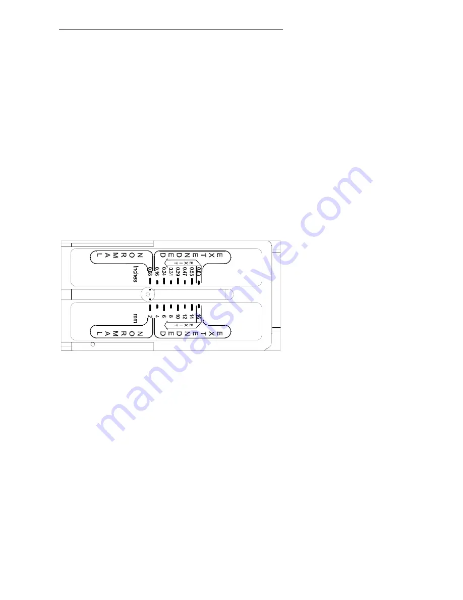
5.2.1  Manual Adjustment for thick media 

 
You can change the insertion slot size (guide plate height) on your 
scanner from 0 to 15 mm (0 to .6”) in small steps so you can fit the 
slot to the thickness of your original. 
 
To change the insertion slot space, open the Original’s Insertion Slot 
cover and set the media thickness adjustment sliders found at each 
side to the same setting. 


Figure 5-2 Media Thickness Settings 

Summary of Contents for Wide Format Color

Page 1: ...Operator s Guide Wide Format Color Monochrome Scanners...

Page 2: ...e 3 8 3 7 Connection through the SCSI interface 3 9 3 7 1 Step 1 Install the SCSI host adapter board 3 9 3 7 2 Step 2 Install the SCSI driver software 3 10 3 7 3 Step 3 Connect the scanner to the PC 3...

Page 3: ...7 Appendix A Important Safety Instructions 7 1 8 Appendix B Regulations 8 1...

Page 4: ...odel if you are unsure whether a feature described in this guide is relevant for your specific scanner For example descriptions in this guide on color calibration and color scanning speeds do not appl...

Page 5: ...ating system see the WIDEsystem TOOLS documentation for details USB port enabled FireWire Port or an SCSI interface kit matching your workstation Note USB and FireWire are not supported on Windows NT...

Page 6: ...oper ventilation is provided See also the Safety Instructions at the end of this operator s guide 3 2 Smart Card Check that the scanner Smart Card is correctly installed contact side downwards and cor...

Page 7: ...equipped for FireWire connectivity Note FireWire is not supported on Windows NT USB USB is a connectivity specification that allows computer peripherals to be attached to a computer and eliminates the...

Page 8: ...accessed from the scanner s back As illustrated in the interface table above the different scanner models support different options for interfacing You will find one of the following types of cable c...

Page 9: ...tion to PC and one for daisy chaining another device USB connector AUX Future purpose connector Figure 3 2 Scanner USB and SCSI Connectors on Cougar Scanners Note The extra SCSI connector is only used...

Page 10: ...connectors Figure 3 3 FireWire SCSI Connector Note The extra SCSI connector and extra FireWire connector are for daisy chaining another device to your system and not for interfacing with another PC R...

Page 11: ...to install a FireWire card To install a FireWire card shutdown your computer and install the card into an empty PCI slot See your computer s user s manual for installation of new hardware and the driv...

Page 12: ...USB interface USB is supported on Windows 98 or above USB is not supported on Windows NT Your computer must have an enabled USB port 3 6 1 Check your USB Port Even if the computer has a USB port it wi...

Page 13: ...ow the steps described below under Unknown device is found message 6 The driver is located on the WIDEsystem TOOLS CD ROM that came with your scanner Insert the CD into your CD drive 7 Follow the inst...

Page 14: ...teps Each step is described in detail in the following sections 1 Install the SCSI host adapter board into an empty slot in PC 2 Install the SCSI driver software that came with the scanner 3 Connect t...

Page 15: ...rted into the scanner and plugged in 3 7 4 Step 4 Set the scanner DIL switches The DIL switches are used for setting up of the scanner s SCSI connection ports and for selection of the scanner test mod...

Page 16: ...it pops open and remove the Smart Card Figure 3 4 Access the DIL switches Important Remember to reinsert the Smart Card when finished setting the DIL switches and before turning power on SCSI DIL Swi...

Page 17: ...3 SCSI device no 0 ON ON ON SCSI device no 1 OFF ON ON SCSI device no 2 ON OFF ON SCSI device no 3 OFF OFF ON SCSI device no 4 ON ON OFF SCSI device no 5 OFF ON OFF SCSI device no 6 ON OFF OFF SCSI d...

Page 18: ...ON Host Computer SCSI CD ROM SCSI C The Scanner is not the last device on the SCSI bus SCANNER Switch 4 must be OFF Host Computer SCSI CD ROM SCSI Must be terminated Note If the scanner is connected...

Page 19: ...use no effect Switch 7 Force boot start up If a malfunction occurred during an update of the scanner firmware this switch forces the scanner into firmware boot mode enabling you to download the firmw...

Page 20: ...e wizard Otherwise a message will inform you that your scanner could not be detected If this is the case turn off power to all connected devices and reboot the system 3 9 Preliminary Maintenance Once...

Page 21: ...plication control area with 3 keys A Paper control area with 2 keys and 1 LED indicator On some scanner models an Automatic Thickness Adjustment Control ATAC key is also available in the Paper control...

Page 22: ...Operator s Panel with ATAC Automatic Thickness Adjustment Control functionality Detailed descriptions of each numbered item follow in the next sections 1 2 3 4 5 6 8 7 Scanner Control area Application...

Page 23: ...fter the Power LED turns yellow as the scanner goes straight into self test mode All the LEDs will light up the Diagnostics LED red and the other LEDs including the Power LED are yellow After self tes...

Page 24: ...adjusting a scan may be issued but quality may be compromised when adjusting is completed the Wait Indicator turns off To allow the scanner to self adjust do not re move original or change Original Pr...

Page 25: ...for activating an application for sending scanned images via E mail 5 Scan Application This button is for activating your scanning application if it is installed on your PC so that when you press the...

Page 26: ...verses the original The original will be fed backwards through the scanner while the key is held down On scanners with ATAC When the scanner is in Automatic Thickness Adjustment Control ATAC mode see...

Page 27: ...adjustment of the guide plate level for scanning thick media The next section of this manual describes thick media scanning in detail Pressing the ATAC key toggles scanner operation between ATAC mode...

Page 28: ...method can be selected from the scanning application Center feeding is always preferable as the original is positioned symmetrically on the feed rollers during scanning The scan area width measured in...

Page 29: ...o you can fit the slot to the thickness of your original This feature adds an extra dimension to scanning possibilities Depending on your scanner model changing the insertion slot height is 5 2 1 Manu...

Page 30: ...ready for thick media scanning 5 2 2 Automatic Thickness Adjustment Control Some scanner models support Automatic Thickness Adjustment Control ATAC Scanners supporting ATAC have an ATAC key on the ope...

Page 31: ...auto adjustment is stored and utilized This means that you should from time to time return to the normal position and especially when turning the scanner on to allow it to auto adjust The Normal posit...

Page 32: ...ther maintenance purposes you have to free the pressure platen On some scanner models the pressure platen can be completely detached from the scanner On scanners with Automatic Thickness Adjustment Co...

Page 33: ...ngers in the insertion slot and flip the cover open 4 The pressure platen with the white metal areas is under the scanner cover Hold the cover open as you clean 5 4 Changing the glass plate Some scann...

Page 34: ...With both arms pull the left and right levers backwards to flip the glass plate upwards towards your body 4 The levers are attached to the scanner chassis with a small hook Lift the levers out of the...

Page 35: ...d color interpretation This works the other way as well scanner calibration must always be preceded by cleaning and camera alignment to get reliable calibration results Scanner Maintenance is very eas...

Page 36: ...efeat or ignore the purpose of the grounding type plug E Do not allow anything to rest on the power cord Do not locate the scanner where persons will walk on the cord F If an extension cord is used wi...

Page 37: ...nditions When the power cord or plug is damaged or frayed If liquid has been spilled into the scanner If the scanner has been exposed to rain or water If the scanner does not operate normally when ope...

Page 38: ...This equipment generates uses and can radiate radio frequency energy and if not installed and used in accordance with the instruction manual may cause harmful interference to radio communications Oper...

Reviews: