3. Each Component Function
Hardware Manual
17
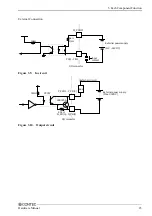
Illustrated below are the peripheral circuits for the data transmission mode setting and terminator setting
switches.
SOUT
SIN
CTS
RTS
DCD
DTR
DSR
RI
SW4
1
8
TxD+
TxD-
RxD+
RxD-
CTS+
CTS-
RTS+
RTS-
Terminator
1/2W 100
Ω
6.2k
Ω
47k
Ω
Vcc
6.2k
Ω
6.2k
Ω
47k
Ω
Vcc
47k
Ω
6.2k
Ω
47k
Ω
ST16C550 equivalent
Figure 3.6. Setting Switch Peripheral Circuits
Summary of Contents for IPC-PT/LS15 Series
Page 5: ...iv Hardware Manual...


