3. External Connection
28
GCOM-2C2-PCI,
GCOM-4C2-PCI, GCOM-8C2-PCI
Connection conversion cable & connection conversion unit (Option)
Connection Conversion Unit for RS-232C(78P
→
25P x 8)
CCU-78F/25M
COM-4ch Board Optional Cable for CCU-78F/25M (2m)
RSS-78M/37M
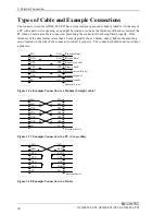
Connection cable (Option)
RS-232C Straight Cable with D-SUB25P (1.8m)
RSS-25M/F
RS-232C Cross Cable with D-SUB25P (1.8m)
RSC-25F
RS-232C Connection Conversion Straight Cable (25M
→
9F, 1.8m) RSS-25M/9F
RS-232C Connection Conversion Straight Cable (25F
→
9M, 1.8m) RSS-25F/9M
RS-232C Connection Conversion Cross Cable (25F
→
9F, 1.8m)
RSC-25F/9F
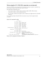
Connecting directly to the port connector
If connecting an external device directly from the connector on the board, use a CN5-D9F or equivalent
connector.
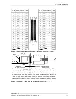
Pin Assignment
37
20
19
1
- Connector used
37-pin D-SUB, male connector
DCLC-J37SAF-20L9 (mfd. by JAE)equivalent
- Applicable connector
17JE-23370-02(D8C) (mfd. by DDK, Male)
FDCD-37P (mfd. by HIROSE, Male)
DC-37P-N (mfd. by JAE, Male)
CN5-D37M (mfd. by CONTEC, Male) (Five connector set)
Screw nut: UNC#4-40(inch screw)
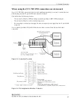
Figure 3.7. Interface Connector < GCOM-4C2-PCI >
19
18
17
16
15
14
13
12
11
10
9
8
7
6
5
4
3
2
1
TxD1
CH1 Transmit Data 1
RTS1
CH1 Request to Send 1
DSR1
CH1 Data Set Ready 1
DTR1
CH1 Data Terminal Ready 1
RI1
CH1 Ring Indicator 1
RxD2
CH2 Receive Data 2
CTS2
CH2 Clear to Send 2
SG2
CH2 Signal Ground 2
DCD2 CH2 Data Carrier Detect 2
TxD4
CH4 Transmit Data 4
RTS4
CH4 Request to Send 4
DSR4
CH4 Data Set Ready 4
DTR4
CH4 Data Terminal Ready 4
RI4
CH4 Ring Indicator 4
RxD3
CH3 Receive Data 3
CTS3
CH3 Clear to Send 3
SG3
CH3 Signal Ground 3
DCD3 CH3 Data Carrier Detect 3
N.C.
37
36
35
34
33
32
31
30
29
28
27
26
25
24
23
22
21
20
CH1 Receive Data 1
RxD1
CH1 Clear to Send 1
CTS1
CH1 Signal Ground 1
SG1
CH1 Data Carrier Detect 1 DCD1
CH2 Transmit Data 2
TxD2
CH2 Request to Send 2
RTS2
CH2 Data Set Ready 2
DSR2
CH2 Data Terminal Ready 2
DTR2
CH2 Ring Indicator 2
RI2
CH4 Receive Data 4
RxD4
CH4 Clear to Send 4
CTS4
CH4 Signal Ground 4
SG4
CH4 Data Carrier Detect 4 DCD4
CH3 Transmit Data 3
TxD3
CH3 Request to Send 3
RTS3
CH3 Data Set Ready 3
DSR3
CH3 Data Terminal Ready 3
DTR3
CH3 Ring Indicator 3
RI3
CN1
Figure 3.8. Pin Assignments of Interface Connector < GCOM-4C2-PCI >
Summary of Contents for GCOM-2C2-PCI
Page 13: ...1 Before Using the Product 8 GCOM 2C2 PCI GCOM 4C2 PCI GCOM 8C2 PCI...
Page 43: ...4 Functions 38 GCOM 2C2 PCI GCOM 4C2 PCI GCOM 8C2 PCI...
Page 46: ...5 About Software GCOM 2C2 PCI GCOM 4C2 PCI GCOM 8C2 PCI 41 CD ROM Directory Structure...
Page 47: ...5 About Software 42 GCOM 2C2 PCI GCOM 4C2 PCI GCOM 8C2 PCI...
Page 52: ...6 About Hardware GCOM 2C2 PCI GCOM 4C2 PCI GCOM 8C2 PCI 47...


