2. Setup
GCOM-2C2-PCI, GCOM-4C2-PCI, GCOM-8C2-PCI
19
Step 4 Checking Operations with the Diagnosis
Program
Use the diagnosis program to check that the board and driver software work normally, thereby you can
confirm that they have been set up correctly.
What is the Diagnosis Program?
These programs perform some simple checks on the board operation.
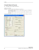
The following describes the procedure for testing using the serial communications diagnostic program
Check Method
Obtain an RS-232C cross cable or a loopback connector. If using a loopback connector, you can test a
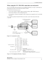
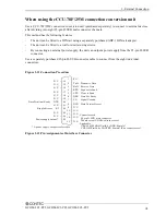
single COM port on its own. The diagram below shows the connections for a loopback connector.
Wiring diagram for loopback connector
<9-pin>
Board side
3
2
7
8
4
6
TxD
RxD
RTS
CTS
DTR
DSR
Board side
TxD
RxD
RTS
CTS
DTR
DSR
<25-pin>
2
3
4
5
20
6
Summary of Contents for GCOM-2C2-PCI
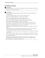
Page 13: ...1 Before Using the Product 8 GCOM 2C2 PCI GCOM 4C2 PCI GCOM 8C2 PCI...
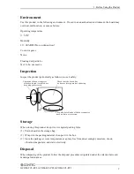
Page 43: ...4 Functions 38 GCOM 2C2 PCI GCOM 4C2 PCI GCOM 8C2 PCI...
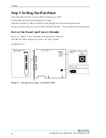
Page 46: ...5 About Software GCOM 2C2 PCI GCOM 4C2 PCI GCOM 8C2 PCI 41 CD ROM Directory Structure...
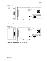
Page 47: ...5 About Software 42 GCOM 2C2 PCI GCOM 4C2 PCI GCOM 8C2 PCI...
Page 52: ...6 About Hardware GCOM 2C2 PCI GCOM 4C2 PCI GCOM 8C2 PCI 47...


