background image

  Installation 


CPS-CNT-3202I Reference Manual (Hardware) 

  36 


2. 


Setting the Configurable Type Module 


CAUTION 


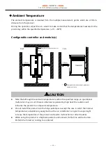
If the modules set side-by side are disconnected during the operation, it can cause damage to 
the product. Set the controller on DIN rail in order to avoid the trouble. 


Always confirm the PWR-LED is turned off before setting or removing the modules. 


Always check the module is firmly fixed on DIN rail with hooks when setting the product. 


ATTENTION 


Si les modules côte-à-côte sont débranchés au cours du fonctionnement, cela risque 
d’endommager le produit. Réglez le contrôleur sur le rail DIN pour éviter tout 
débranchement. 


Confirmez toujours que la DEL PWR est éteinte avant de fixer ou de déposer les modules. 


Vérifiez toujours si le module est solidement fixé sur le rail DIN avec les crochets lors de 
l'insertion du produit. 


How to Set 

1


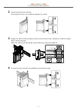
First, slide the attached end cover to remove it from the product that is mounted on the DIN 
Rail. 


Summary of Contents for CONPROSYS CPS-CNT-3202I

Page 1: ...ual Hardware CONTENTS Counter Module CPS CNT 3202I Introduction 4 Safety Precautions 11 Product Nomenclature and Function 19 Installation 32 Appendix 46 Optional Products 52 Customer Support and Inquiry 54 Index 56 ...

Page 2: ...enclature of Product Components 20 2 Description of Product Components 21 1 Stack Bus 21 2 LED Indicator 21 3 Counter Input Connector 22 4 DIP Switch 23 3 Types and Operations of Pulse Signals 24 1 Types of Pulse Signals 24 2 Pulse Input 24 3 Multiplication of Count Input 26 4 Count Clear 27 4 Other Function 29 1 Compare Register 29 2 Digital Filter 29 3 Programmable Timer 30 4 One shot Pulse 30 I...

Page 3: ...ontents Appendix 46 1 Specifications 47 1 Specifications 47 2 Physical Dimensions 50 3 The Details of Model Name 51 Optional Products 52 1 Optional Products 53 Customer Support and Inquiry 54 1 Services 55 Index 56 ...

Page 4: ... 4 Introduction This section provides necessary information of the product such as the outline bundled items and manuals before actual use ...

Page 5: ... Read this when setting up the product This describes the required items for setup and configuration procedure Download from the Contec website PDF Reference Manual Hardware Read this when operating the product This describes the hardware aspects such as functions and settings Download from the Contec website PDF Reference Manual Software Read this when setting up the CONPROSYS WEB Setting This de...

Page 6: ...e product visit our website to check the firmware version and update to the latest one if necessary Updating firmware to the latest version will resolve troubles and stabilize the operation Download https www contec com download Refer to the Reference Manual Software for the details of the firmware updating ...

Page 7: ... counts input pulse signals from external devices to the configurable controller of our CONPROSYS series It has two channels of 32 bit up down counters allowing external devices such as a rotary encoder and a linear scale to be connected Examples are given for detecting a position of the table of a machine tool and detecting a change in weight ...

Page 8: ...erminals can be added a digital filter and the setting can be performed by software Output circuits include zener diodes for surge voltage protection Zener diodes are connected to the output circuits to protect against surge voltages The rated output is 35VDC 50mA to the maximum per channel Compact design Compact design 25 2 W 94 7 D 124 8 H features flexibility in installation Adaptable to a temp...

Page 9: ...h LED for an operation check The product has LED for an operation check which helps you visually confirm the communication status of each interface No electrolytic capacitor battery No electrolytic capacitor is used The Contec is creating the product with a longer life ...

Page 10: ...guration List The product consists of the items listed below Check with the following list that your package is complete If you discover damaged or missing items contact your retailer Product 1 Product Guide 1 Warranty Certificate 1 Serial Number Label 1 10 pin Connector 2 ...

Page 11: ... 11 Safety Precautions Understand the following definitions and precautions to use the product safely Never fail to read them before using the product ...

Page 12: ...ate injury or in property damage Informations de sécurité Ce document contient des informations relatives à la sécurité sous utilisation des symboles suivant afin d éviter tout accident risquant d entraîner des blessures ou la mort et la destruction de l équipement et des ressources Veillez à comprendre les significations de ces mots signalétiques pour utiliser l équipement en toute sécurité DANGE...

Page 13: ...r power medical equipment or other applications that require a very high level of reliability Do not use the product in such applications If using the product in applications where safety is critical such as in railways automotive or disaster prevention or security systems please contact your retailer CAUTION Be certain the following requirements are satisfied when using the product Indoor use Alt...

Page 14: ... of failure or abnormality foul smells or excessive heat generation unplug the power cables immediately and contact your retailer To connect with peripherals use a grounded shielded cable To clean the product wipe it gently with a soft cloth dampened with either water or mild detergent Do not use chemicals or a volatile solvent such as benzene or thinner to prevent the paint to be scraped or disco...

Page 15: ...d herein Précautions d emploi DANGER Ne pas utiliser le produit dans des endroits exposés à des gaz inflammables ou corrosifs L exposition peut provoquer une explosion un choc électrique ou une défaillance Ne pas mettre le dispositif en contact avec des substances étrangères particules métalliques substances inflammables liquides etc Faute de quoi le contact peut provoquer un incendie ou un choc é...

Page 16: ...xemple un panneau de contrôle à l épreuve de la poussière Éviter d utiliser le produit dans des endroits susceptibles aux chocs ou aux vibrations hors de la plage précisée ou de le ranger dans ces endroits Lors du transport du produit prendre les mesures qui s imposent pour éviter tout choc ou toute vibration directement sur le produit Résistance aux impacts 15 G 11 ms ci dessous Utiliser le produ...

Page 17: ... les voies d accès câble de signal etc Consulter un spécialiste pour la sélection l achat et l installation d un dispositif contre les surtensions Respecter les procédures d élimination précisées dans les lois et les ordonnances municipales pertinentes lors de l élimination du produit Alimentation électrique du produit et E S numérique Pour une certification UL il est obligatoire de raccorder les ...

Page 18: ...esigned to provide reasonable protection against harmful interference when the equipment is operated in a commercial environment This equipment generates uses and can radiate radio frequency energy and if not installed and used in accordance with the instruction manual may cause harmful interference to radio communications Operation of this equipment in a residential area is likely to cause harmfu...

Page 19: ... 19 Product Nomenclature and Function This section describes product component names and their functions pin assignment of each connector ...

Page 20: ...n the figure below No Name Function 1 Stack Bus Used for power supply and communication with the configurable type module 2 LED Indicator This indicates status of the product 3 Counter Input Connector This is a connector for counter input Use the 10 pin connector included in the package 4 DIP Switch Used for voltage setting of external power supply 2 3 1 4 ...

Page 21: ...sous tension alimentation active Confirmez toujours que la DEL PWR est éteinte avant de fixer ou de déposer les appareils 2 LED Indicator Status of the product is indicated by ON OFF and flashing of LED The meaning of each LED is described below Color and Description LED Color Display Description STATUS Green ON Power has been supplied Red ON It lights up when error occurs Green Flashing It flashe...

Page 22: ...to external power Connector type DEGSON 15EDGKC 3 81 10P 13 00AH or equivalent Pin Assignment Pin No Signal Name Description 1 PCOM Positive common of input signal It connects the positive side of external power 2 PA For phase A input 3 PB For phase B input 4 PZ For phase Z input 5 PDI For general purpose input 6 EQ P Positive common of match signal output It connects the positive side of external...

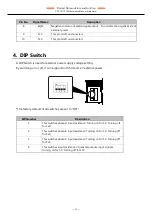
Page 23: ...wer supply voltage setting By switching on or off it can support both 5V and 12V external power The factory default of all switches are set to OFF SW Number Description 1 This switches phase A input resistance Turning on for 5 V Turning off for 12V 2 This switches phase B input resistance Turning on for 5 V Turning off for 12V 3 This switches phase Z input resistance Turning on for 5 V Turning off...

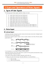
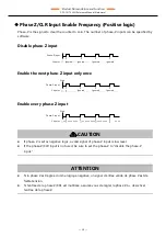
Page 24: ...t with Gate Control Asynchronous Clear Multiply by 2 2 Pulse Input 2 phase Input Two phase pulse input consists of a phase A pulse advanced signal and a phase B delayed signal pulse that have 90 of phase difference If the phase Z reference position signal is used a Z pulse will reset count value of the two phase pulse input to zero Count operation for incremental counting in the CW direction When ...

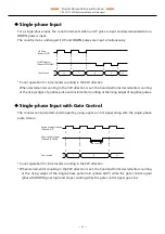
Page 25: ... incremental counting at the rising edges of negative pulses Single phase Input with Gate Control The counter can be started and stopped by using a gate control signal along with the single phase pulse stream Count operation for incremental counting in the CW direction When decremental counting in the CW direction is set the board performs decremental counting at the rising edges of the single pha...

Page 26: ... when count input multiplication is set During 2 Phase input During Single Phase input Single phase input is set only to multiply by 1 mode Multiply by 2 or any other higher setting is not available Single phase input with gate control attached Multiply by 1 Multiply by 2 Multiply by 4 Multiply by 1 Multiply by 2 Multiply by 4 When clockwise is specified When counterclockwise is specified Multiply...

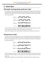
Page 27: ...negative logic is used the signal is enabled while the phase Z input remains low Asynchronous Clear If a counter is set for CW clockwise direction Up count and phase Z positive logic whenever the phase Z input goes high will reset the count value no matter which signal level the phase A and phase B is The counter will start counting from next rising edge of the phase A no matter what signal level ...

Page 28: ... phase Z is set as negative logic a valid signal of phase Z input is low level If the phase Z CLR input is not used be sure to set the phase Z to disable the phase Z input ATTENTION Si la phase Z est réglée comme logique négative un signal d entrée valide de phase Z est de faible tension Si l entrée de la phase Z CRL est inutilisée assurez vous de régler la phase Z à désactiver l entrée de la phas...

Page 29: ... input to the counter and or into A B and Z phase signals Operation Principle The sampling clock cycle of the digital filter is determined by clock setting data for the digital filter When the input signal is sampled with this sampling clock and if HIGH or LOW is detected for duration of four continuous clocks the digital filter outputs HIGH or LOW and communicates it to the counter circuit If a l...

Page 30: ...a delay of 0 4μsec L état initial est réglé à 0 1 seconde Quand le cycle n est pas précisé il est aussi à 0 1μsec par défaut Selon les signaux parasites un délai de plus de quatre cycles d horloge réglé peut survenir 3 Programmable Timer The programmable timer can generate interrupts at cycles according to a 32 bit setting data The timer can be set in a range of 1msec through 200sec The setting ca...

Page 31: ...tate is set to pulse width 0 do not output Pulse widths may slightly vary depending on the specifications of a connected load ATTENTION L état par défaut est réglé à largeur impulsion 0 pas de sortie Les largeurs d impulsion peuvent varier légèrement selon les caractéristiques d une charge raccordée ...

Page 32: ... 32 Installation This section describes how to mount the product on a DIN rail and to connect to an external device with a cable ...

Page 33: ... 1 Install the Product 1 Installation Conditions Installation Orientation Install the product in the orientations shown below 0 C Other orientations may cause problems such as malfunctions due to inadequate heat dissipation Orientation for DIN rail Mounting ...

Page 34: ...an operational malfunction may occur if there is other device generating high heat the radiation will influence the product to increase its temperature Do not install this product into the fully sealed space except the case in which the internal temperature is adjustable by equipment such as air conditioner Long term usage might increase the temperature of the product and lead to malfunctions or o...

Page 35: ...e température du produit N installez pas le produit dans un espace entièrement scellé sauf dans les cas où la température interne est réglée par un appareil comme un climatiseur Une utilisation sur une période prolongée peut accroître la température et mener à une défaillance ou à d autres problèmes Lors de l utilisation du produit dans un environnement à température élevée la durée de vie du prod...

Page 36: ... module is firmly fixed on DIN rail with hooks when setting the product ATTENTION Si les modules côte à côte sont débranchés au cours du fonctionnement cela risque d endommager le produit Réglez le contrôleur sur le rail DIN pour éviter tout débranchement Confirmez toujours que la DEL PWR est éteinte avant de fixer ou de déposer les modules Vérifiez toujours si le module est solidement fixé sur le...

Page 37: ...crewdriver to unlock 3 Engage the side rail of the setting module to the side rail of the controller or another module that is already mounted When the rails fit slide the setting module all the way toward the DIN rail 4 Fix and secure the module on the DIN rail by locking the hooks 山路を登りながら Module side rail Controller side rail ...

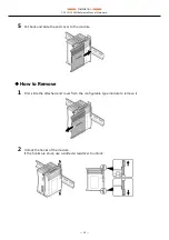
Page 38: ...rdware 38 5 Put back and slide the end cover to the module How to Remove 1 First slide the attached end cover from the configurable type module to remove it 2 Unlock the hooks of the module If the hooks are stuck use a slotted screwdriver to unlock ...

Page 39: ...ver as leverage Insert a slotted screwdriver the point should be smaller than 4 5mm into a hole see the figure below By using the screwdriver as leverage move it downward in the direction of the arrow to unlock By rotating the screwdriver Place the slotted screwdriver the point should be smaller than 8mm as shown in the figure Rotate the screwdriver 90 degree in either direction A projection tip t...

Page 40: ... Installation CPS CNT 3202I Reference Manual Hardware 40 3 With the hooks unlocked pull the module toward you 4 Put back the end cover to the controller ...

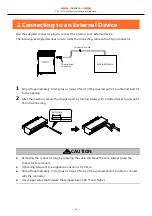
Page 41: ... it to the opening 2 After the insertion secure the stripped part by turning screws with a slotted driver to prevent it from disconnecting CAUTION Removing the connector plug by grasping the cable can break the wire Always grasp the connector to remove it Tightening torque of the supplied connector is 0 19 N m Strip off approximately 9 mm plus or minus 0 5mm of the covered part of a cable to conne...

Page 42: ...e vous risquez de briser le fil Saisissez toujours le connecteur pour le retirer Utilisez un couple de 0 19 N m pour le connecteur présent Dénudez environ 9 mm plus ou moins 0 5 mm de la section gainée du câble pour le raccorder au connecteur Veuillez utiliser des fils de cuivre qui résistent à une température de 90 degrés Celsius et plus ...

Page 43: ...in the page 22 for details of the counter input connector and pin assignment Opto coupler Isolated Input Circuit Opto coupler isolated input connection with a rotary encoder or a linear scale open collector output circuit is shown in the figure below The maximum input frequency 500 kHz For a two phase input connect both phase A and phase B For a single phase input connect to either phase A or phas...

Page 44: ...eurs DIP sur le côté du produit pour utiliser une alimentation externe de 5 V Désactivez tous les commutateurs DIP sur le côté du produit pour utiliser une alimentation externe de 12 V Example Connection with a Rotary Encoder CPS CNT 3202I Power supply 0V Shield Encoder Phase A Phase B Phase Z Phase A Phase B Phase Z 5 or 12VDC CH0 STATUS PCOM A DI Z B CNT 3202I CH1 CH0 PA PB PZ PDI EQ P EQ EQ N N...

Page 45: ...Linear Scale One shot Pulse Output Connection When the count value of each channel and the user set value match the circuit outputs a matched signal for one shot 1 pulse The pulse wide setting can be done on Web browser menu Refer to the Reference Manual Software for setting procedure ...

Page 46: ... 46 Appendix This section lists the specifications and the physical dimensions of the product and the details of model name ...

Page 47: ...n setting 12V external power 13 2V 25mA Input ON current 12mA or more Input OFF current 0 8mA or less Response frequency 500kHz duty 50 Max Interrupt level One interrupt caused upon channel count match or timer time out External power 1 5V 5 or 12VDC 10 Min 200mA Opto coupler input current Opto coupler primary current 15 25mA Digital filter 0 1µsec 1056 1µsec can be independently set for each chan...

Page 48: ...ces 3 81mm pitch 10 pin terminal Applicable wire AWG28 16 LED Status Green Red Current consumption 0 1A Max Physical dimensions mm 25 2 W 94 7 D 124 8 H No projection included Weight 200g Installation method Quick mounting on the 35mm DIN rail 1 Use 5V or 12V power appropriately as an input resistance can be switched by DIP switch CAUTION You can set the modules as you desire to the configurable c...

Page 49: ...61000 4 4 Level 3 Static electricity resistance Touch 4kV IEC61000 4 2 Level 2 EN61000 4 2 Level 2 Air 8kV IEC61000 4 2 Level 3 EN61000 4 2 Level 3 Vibration resistance Sweep resistance 10 57Hz 2 semi amplitude vibration 0 15mm 57 150Hz 2 0G 40minutes each in X Y and Z directions JIS C60068 2 6 compliant IEC60068 2 6 compliant Shock resistance 15G half sine shock for 11ms in X Y and Z directions J...

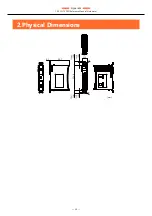
Page 50: ... Appendix CPS CNT 3202I Reference Manual Hardware 50 2 Physical Dimensions 25 2 124 8 14 18 φ4 φ4 14 18 mm 94 7 5 1 ...

Page 51: ...ardware 51 3 The Details of Model Name Details of the model name are described below No Item Description 1 Interface CNT Counter 2 Resolution 32 32 bit 3 Channel 02 2 Channels 4 Isolution I Bus Isolation CPS CNT 32 02 I CONPROSYS Series 2 3 1 4 ...

Page 52: ... 52 Optional Products This section lists optional items that can be used along with the product ...

Page 53: ...figurable Type CPU module OPC UA server MTConnect CPS MCS341G DS1 130 Configurable Type CPU module 3GWAN CPS MCS341Q DS1 131 Configurable Type CPU module 920MHz LAN CPS ECS341 1 011 Ether CAT Slave module DIN rail fitting power supply CPS PWD 90AW24 01 Fitting power supply 90W Output 100 240VAC Output 24VDC 3 8 A CPS PWD 30AW24 01 Fitting power supply 30W Output 100 240VAC Output 24VDC 1 3 A Visit...

Page 54: ... 54 Customer Support and Inquiry CONTEC provides the following support services for you to use CONTEC products more efficiently and comfortably ...

Page 55: ... the useful information including product manuals that can be downloaded through the Contec website Download https www contec com download You can download updated driver software firmware and differential manuals in several languages Membership registration myCONTEC is required to use the services ...

Page 56: ... 56 Index ...
Page 57: ... Index CPS CNT 3202I Reference Manual Hardware 57 Revision History MONTH YEAR Summary of Changes November 2016 The First Edition June 2018 Changed the layout of the manual ...
Page 58: ...55 0025 Japan https www contec com No part of this document may be copied or reproduced in any form by any means without prior written consent of CONTEC CO LTD CPS CNT 3202I Reference Manual Hardware NA05206 LYUG043 06152018_rev3 11042016 June 2018 Edition ...

Reviews: