9
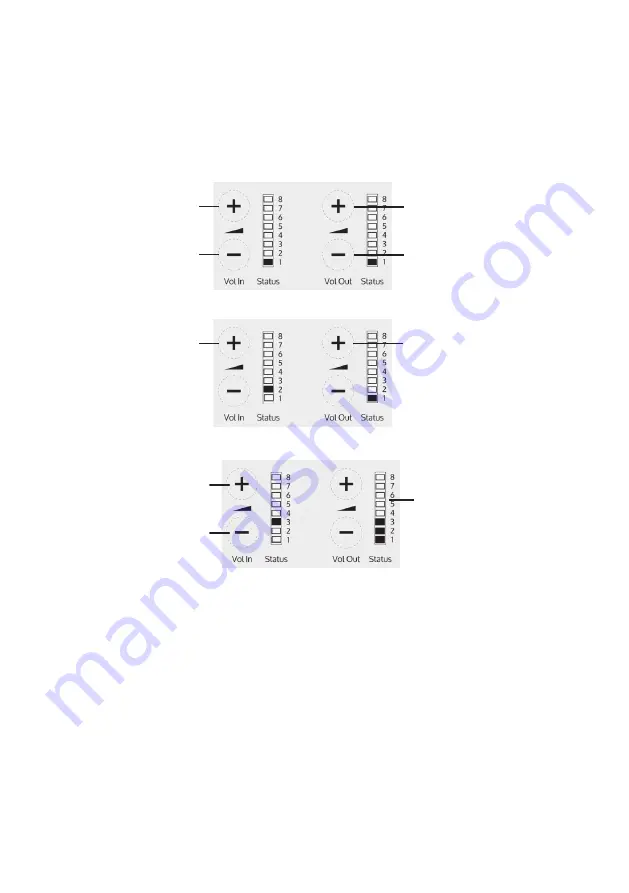
Setup Area 3: Hearing Loop Drive Adjustment (LED 3 flashes)
Increase drive
Decrease drive
Vol I
n
Sta
tus
8
7
6
5
4
3
2
1
Vol O
ut
STS-
A31
CO
2
con
tacta
Vol I
n
Sta
tus
8
7
6
5
4
3
2
1
Vol O
ut
STS-
A31
CO
2
con
tacta
Vol I
n
Sta
tus
8
7
6
5
4
3
2
1
Vol O
ut
STS-
A31
CO
2
con
tacta
LEDs illuminate to
display loop drive
voltage
If the amplifier does not have a loop attached, turn off the red loop fault LED
8 by adjusting the drive down to off.
Please note:
If the amplifier detects an error in its settings memory it will
restore itself to factory default settings.
Whilst in engineers mode, there are 3 editable setup areas. You will always
enter setup area 1 first. The green Volume In LED bar will flash to indicate
which setup area you are in.
Setup Areas
Setup Area 2: Ducking Adjustment (LED 2 flashes)
Setup Area 1: Maximum Volume Adjustment (LED 1 flashes)
Increase maximum
staff volume level
Decrease maximum
staff volume level
Increase maximum
customer volume level
Decrease maximum
customer volume level
Increase
ducking level
Decrease
ducking level
Ducking on
(Vol Out LED 1 illuminates)
Ducking off
(Vol Out LED 1 turns off)
Summary of Contents for STS-K009
Page 13: ......
Page 14: ......
Page 15: ......
Page 16: ...Contact your local distributor for further information www contacta co uk ...


