


26
Store modules tightly drawn together (≤ 1 mm gap)
Between all store modules are 2 M20 bolts and the
storage modules are aligned with each other.
All cap nuts on the connecting rods and if necessary all
extensions are installed and tight
All 2" barrel nuts are evenly tightened: Ensure the
same free thread length behind the cylinder nuts on
both sides of the loading and unloading tubes.
6�7 Pressure test
The following points must be documented:
NOTE
:
Each intermediate module (on top) and each end
module (on front) has a 1/2" connection for venting of the
store while filling. In operation venting should be carried
out by an air separator mounted at the outlet of the store on
the top loading and unloading pipe, see planning aid 3.5.
NOTE
: The store is drained from the lowest pipe connection.
When emptying the store air should be introduced into the
top loading/unloading pipe.
WARNING:
Accident/hazard due to failure to observe the
safety regulations!
Observe the relevant country-specific standards, health and
safety regulations and rules for the operation of pressure
tests.
NOTE:
Damage of the heating system due to over pressure!
Don not connect the store to the heating system during
pressure testing.
Slowly fill the store with water. Vent the store through the air
vent and the top connection.
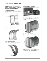
The pressure profiles are fitted to both ends of store over the
2” connections and held in place with 4 x M6 bolts.
Two barrel nuts with washers are screwed onto the top and
bottom loading and unloading pipes. The 2” barrel nuts
are initially tightened on both sides – if necessary, by the
distance (X + 1 mm) missing in the above control.
The remaining 2” barrel nuts, together with the 2” washers,
are hand-tightened on both sides of the loading and unlo-
ading pipes in order to position the pipes correctly. Then
tighten the cylinder nuts evenly on each side with at least 1
turn, maximum 1.5 turns, in order to ensure the sealing of
the end sleeve against the O-ring seal.
Loosen the uppermost and lowermost cylinder nuts again,
tighten again by hand, and tighten with 1 to 1.5 revolutions
on both sides.
The connecting pipes can now be installed.
Observe the
instructions in section 3 Planning aids!
6�6 Control module Assembly
The following points must be documented:
T D M A - VA R I C A L :
Assembly instructions