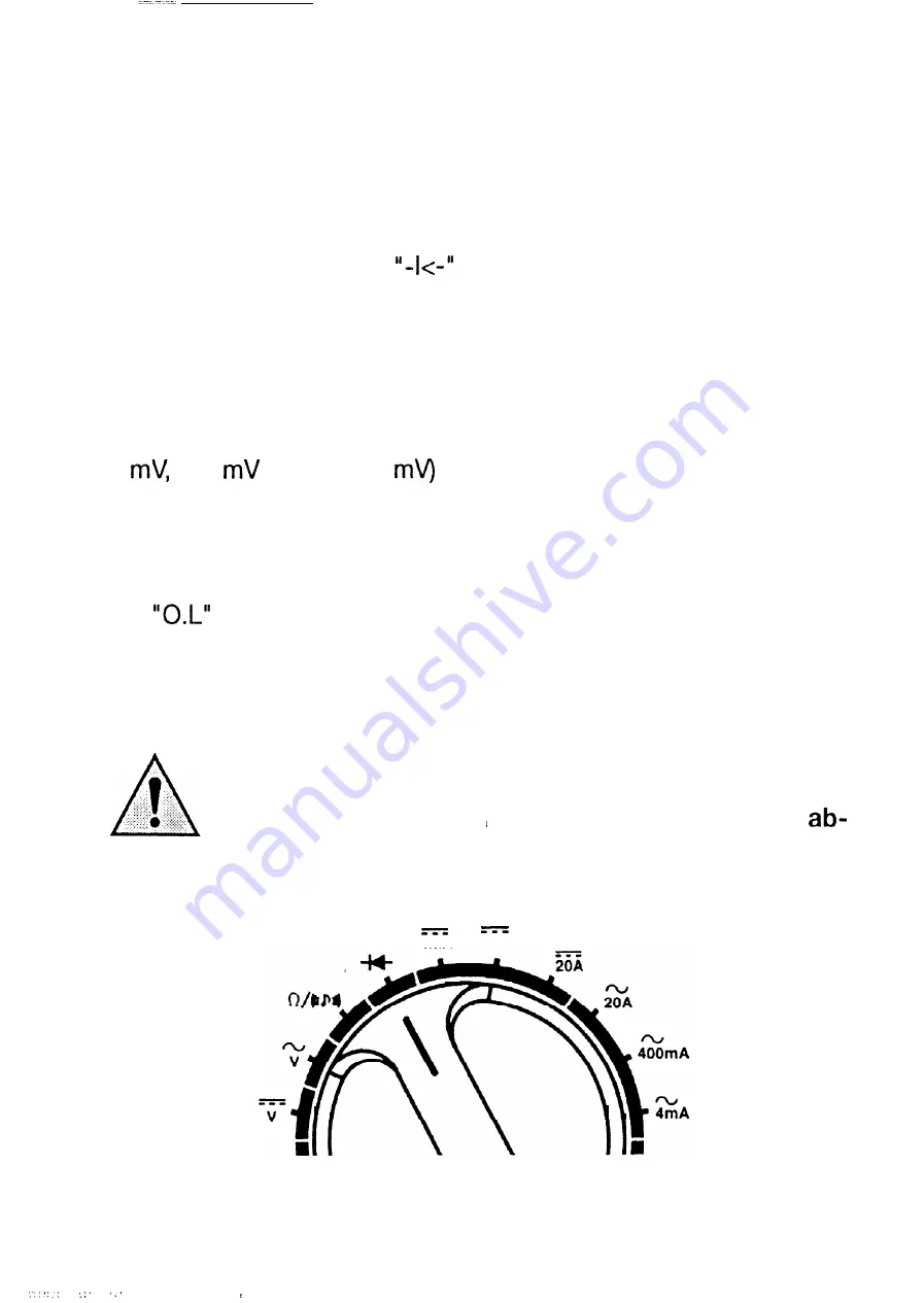
G Diode test
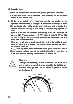
To measure diodes or semiconductor paths, proceed as follows:
I. Connect the black test lead to the COM socket and the red test
lead to the V/Ohm socket.
2. Set the rotary switch to
and connect the test probes to the
.
object to be measured, a voltage-free semiconductor path, with
the red test probe to the anode and the black test probe to the
cathode (which is usually indicated by a coloured ring, spot or si-
milar).
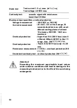
If you test a diode path in the conducting direction, a voltage of
approx. 0.25 V (germanium) or 0.7 V (silicon) up to’2.0 V (or 250
700
up to 2000
will be measured provided that the
diode path is not defective.
If the test leads are interchanged, i.e. red to the cathode and
black to the anode, then the non-conducting direction of the di-
ode path is checked.
If
is displayed, then the diode is in good condition. If on
the contrary a voltage value is indicated, then either the object to
be measured is incorrectly connected or is defective.
During diode testing,
any circuit into which
solutely voltage-free.
be discharged.
Attention!
make sure that
it may possibly
All capacitors
4 m A
400mA
the diode and
be built is
present must
56
,
---

