background image

Handling, Putting into operation

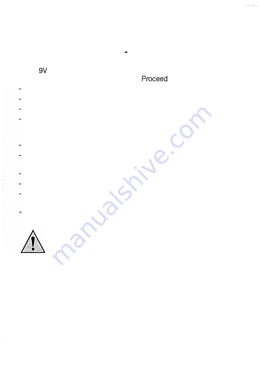
A Installation of batteries   changing batteries

For the measuring instrument to function perfectly, it must be fitted

with a 

 battery. When the change-battery symbol appears in the

display, the batteries must be replaced. 

 as follows:

Disconnect the unit from the circuit being measured,

remove the measuring leads from the measuring instrument,

switch it off and

with a suitable crosshead screwdriver, unscrew the fixing screws

in the lower part of the case at the centre top, bottom left and
bottom right.

Now carefully remove the cover.

Remove the used battery now revealed from the battery com-

partment,

disconnect it from the connecting clips and

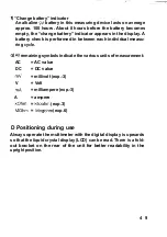
replace the battery with a new one of the same type.

After successfully replacing the battery place it in the battery
compartment and carefully close this once more.

When closing the battery compartment, take care that the

red/black connecting clip leads do not become trapped.

Do not in any event operate the measuring device

when opened! Danger to life!

Do not leave used batteries in the unit, because

even leak-proof batteries can corrode and thereby

release chemicals, which are both damaging to
health and can destroy the battery compartment.

Used batteries are to be treated as waste requiring

special handling and must therefore be disposed of
without harming the environment. Special collection

containers are provided for this purpose by specia-

list dealers and in scrap yards.

43

Summary of Contents for ME-42

Page 1: ...12 99 D Digitalmultimeter M E 4 2 Seite 4 34 Digital Multimeter M E 4 2 Page 35 64 Multimktre numbrique M E 4 2 Page 65 98 G9 Digitale multimeter M E 4 2 Pagina 99 129 Best Nr Item No No de commande...

Page 2: ...f contents with page numbers can be found on page 38 F Ce mode d emploi appartient a ce produit II contient des recommandations en ce qui concerne sa mise en service et samanutention Veuillez en tenir...

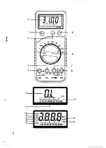
Page 3: ...1 I f 9 1 2 6 I c 20A mA COM V Q j 3 4 7 8 3...

Page 4: ...ble national and European directives Conformance to the se has been proven the relevant documents are lodged with the manufacturer To maintain this condition and to guarantee safe operation the user m...

Page 5: ...performed under unfavourable ambient conditions Unfavourable ambient conditions include l wetness or excessive humidity l dust and combustible gases fumes or solvents l thunderstorms or storm conditi...

Page 6: ...is measuring input is protected with a 20 A fuse and is suita ble for DC and AC currents up to max 20 A max 30 s durati on with 15 minute pause between measurements mA input This input is for measurin...

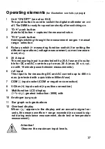
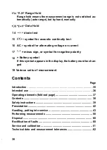
Page 7: ...sign or symbol for negative polarity 18 Battery symbol If this symbol appears in the display the battery must be chan ged 19 Various units of measurement Contents Page Introduction 35 Intended use 36...

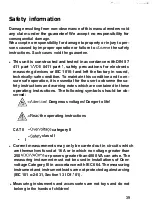
Page 8: ...al for the user to observe the sa fety instructions and warning notes which are contained in these operating instructions The following symbols should be ob served c g A i I cr Attention Dangerous vol...

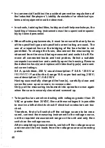
Page 9: ...and replace with identical type s and nomi nal current ratings 0 8 A quick blow 250 V usual description F 0 8 A 250 V or F800mAI250Vand for the A range 15 A super fast acting 250 V usual description F...

Page 10: ...s or under adverse environmental conditions in which inflammable gas fu mes or dust are present or can occur For your own safety it is essential to avoid the measuring instrument or its wiring beco mi...

Page 11: ...vide a complete picture for many measuring tasks The unit has an AUTO RANGE feature such that with different measurements the currently correct measuring range is always set In addition the DMM can be...

Page 12: ...tment disconnect it from the connecting clips and replace the battery with a new one of the same type After successfully replacing the battery place it in the battery compartment and carefully close t...

Page 13: ...n dealing with voltages greater than 25 V AC or 35 V DC _ Attentioh _ A i _ Never exceed the maximum input levels because y jj l I _ otherwise damage to the measuring instrument can endanger life C Pu...

Page 14: ...on D H again and the display returns to the instantaneous measurement R H 3 On pressing this button once the symbol R H for Range Hold appears in the display and the function Auto Ran ge automatic ran...

Page 15: ...measurement common socket means minus or or earth socket d V Ohm socket The red measuring lead must be plugged into this socket to carry out voltage frequency or resistance measurements conti nuity ch...

Page 16: ...lay explanation and symbols a Digital Anzeige The display can indicate up to 3999 and with negative volta ges or reversed polarity the polarity is automatically indicated There are also three decimal...

Page 17: ...old manual range selection After this button is pressed once the symbol R H for Range Hold appears in the display and the function Auto Range automatic range changing is no longer active Each time thi...

Page 18: ...ndividual measu ring cycle g All remaining symbols indicate the various units of measurement AC AC value DC DC value mV millivolt exp 3 V Volt mA milliampere exp 3 A ampere kOhm kiloohm exp 3 MOhm Meg...

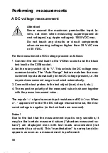
Page 19: ...ature matches the mea surement input automatically to the DC voltage present i e the required measurement range is selected automatically 3 Connect the test probes to the test object load circuit etc...

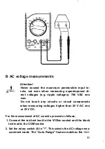
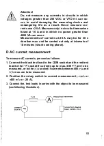
Page 20: ...50 VAC rms max Do not touch any circuits or circuit components when measuring voltages higher than 25 V AC rms or 35 V DC For the measurement of AC currents proceed as follows 1 Connect the red test l...

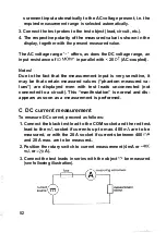
Page 21: ...ay be that certain measured values phantom measured va lues are displayed even with test leads unconnected not connected to a circuit This manifestation is normal and dis appears as soon as a measurem...

Page 22: ...ation max and be carried out only at intervals of 15 minutes shunt cooling phase D AC current measurement To measure AC currents proceed as follows 1 Connect the black test lead to the COM socket and...

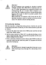
Page 23: ...esting With this function voltage free wiring fuses circuits etc can be acoustically tested for continuity For this measurement proceed as follows 1 Connect the black test lead to the COM socket and t...

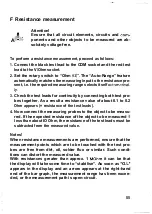
Page 24: ...ult a resistance value of about 0 1 to 0 2 Ohm appears resistance of the test leads Now connect the measuring probes to the object to be measu red If the expected resistance of the object to be measur...

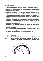
Page 25: ...e of approx 0 25 V germanium or 0 7 V silicon up to 2 0 V or 250 mV 700 mV up to 2000 mV will be measured provided that the diode path is not defective If the test leads are interchanged i e red to th...

Page 26: ...i sed and evaluated The measuring rate here is approx 2 3 mea surements per second I Using the multimeter in connection with a com puter An extensive Windows software package floppy disk and interface...

Page 27: ...ruction s presuppose basic knowledge of the various MS DOS commands and an available hard disk If the user has insufficient or no basic knowledge of MS DOS commands the MS DOS manual must be consulted...

Page 28: ...Windows Insert the floppy disk into the appropriate disk drive A or B In Program Manager open the file window and click Run with the mouse As a result a dialog box with a command line ap pears Type th...

Page 29: ...haracter code bit ASCII Parity keine Stop bits 2 Disposal If despite a good 9V battery supply and intact fuses the digital mul timeter does not function or is no longer repairable then it must be disp...

Page 30: ...maintenance re pair or exchange of parts or assemblies requiring opening of the unit the unit must be disconnected from all voltage sources and measurement cir cuits If adjustment maintenance or repai...

Page 31: ...rs metal brushes or similar for cleaning Technical data and measurement tolerances Technical data Display Maximum rate of measurement Maximum AC DC input current Operating temperature Storage temperat...

Page 32: ...0 mV 750 v 1 5 5dgts 1 V Valid for frequency range from 40 Hz to 100 Hz in the 400 mV range Valid for frequency range from 40 Hz to 400 Hz in other ranges DC current 4mA 0 8 3dgts 1 uA 400 mA I 2 3dgt...

Page 33: ...e of at least 15 minutes 250 VDC VAC rms maximum Overload protection Super fast 15 A 250 V fuse size 6 x 30mm 200mA AC DC in the mA range max 250 VDCNACrms Overload protection Fast 0 8 A 250 V fuse si...

Page 34: ...e of print We reserve the right to change the technical or physical specifications 0Copyright1999byConradElectronicGmbtl PrintedinGermany F Note de Wditeur Cette notice est une publication de la sock...

Reviews: