
fmGenie Diversity Soundfield
B44FDIVINS – fmGenie Diversity Soundfield Installation Instructions V1.3
5
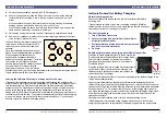
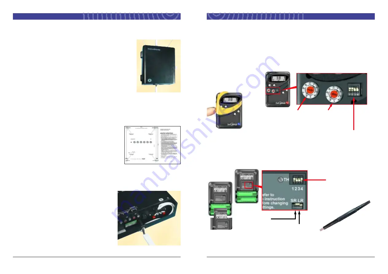
The display on the
transmitter shows which
channel is selected.
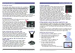
5. Setting up and testing the system
fmGenie transmitter information
General instructions for using the fmGenie transmitter are included in the Tutor
courtesy card.
Set to LR if MLx or cochlear implant processors are being used with a personal fm
system in the classroom.
For further information on the fmGenie transmitter,
please refer to the fmGenie Information &
Instruction Booklet.
fmGenie
‘twiddling
stick’ adjustment
tool – for changing
channel settings or
adjusting Diversity mute
level.
Factory settings:
UP, DOWN, DOWN, UP
Factory settings
UP, UP, DOWN, DOWN
To change the default channel
reselect using the tool supplied
tens units
Normal
MLx or cochlear implant
processors if necessary
Tx underflash switch settings
Tx rear battery compartment switch settings
4
B44FDIVINS – fmGenie Diversity Soundfield Installation Instructions V1.3
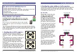
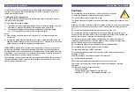
3. Deciding where to mount the fmGenie Diversity
Receiver/amplifier
This is usually best done by discussing the options with the
school staff. Make sure that there is adequate access to
open the door and operate the controls!
The two aerials must be used fully extended in a 60° ‘V’
shape preferably ‘flat’ to where the teacher will normally
stand – away from metal racking, pipes, metal building
frames etc. otherwise the quality of radio reception will be
reduced.
It should not be necessary to adjust the controls during a
lesson so the fmGenie Diversity unit does not actually need
to be beside the teacher although it is a good idea to mount it near to where a TV or
smart board projector might be used. Mounting the unit away from little fingers is also a
good idea(!) and of course do not forget that you also need a 13A mains socket to
power the system.
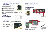
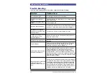
4. Install the system
fmGenie Diversity Wall Mounting
There is an separate A3 sheet which has a template and
guidance for mounting the fmGenie Diversity wall unit.
Connecting the speaker wiring
1
Pass the two speaker cables from behind the unit through the rubber grommet
with the mains cable, around the right hand corner of the unit and through the
speaker cable clamp. See the photograph below.
2
Prepare the speaker cable ends.
3
Place each speaker cable pair into the
appropriate connector, observing the correct
polarity.
4
Lay the speaker cables on top of each other
and tighten the cable clamp.
Lower trunking
Upper trunking
Speaker cables
come from behind
the unit, through the
cable clamp to the
connectors
fmGenie Diversity Soundfield


