background image

DX-1S DIGITAL PABX - MFC98 Manual

4-5

4.9 

RUNNING MFC98 THE FIRST TIME


The DX-1S System is switched on and connection between DX-1S and MFC98 is ready.


Execute MFC98 from the icon at desktop or START | PROGRAM | MFC98.

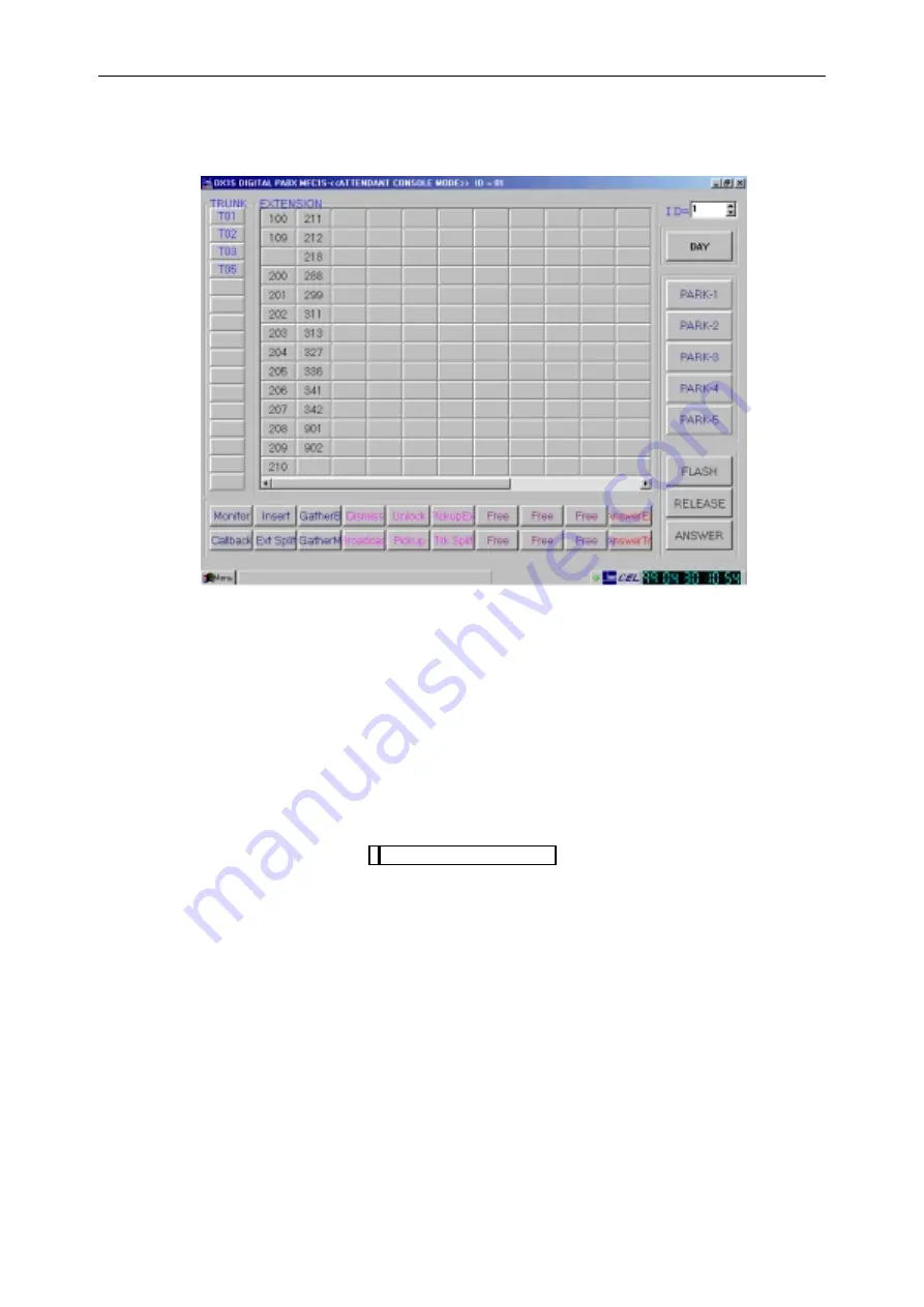
Figure 4-3 MFC98 ATTENDANT CONSOLE MODE SCREEN


If the System Status Light at the lower right area of screen is blinking, it indicates the communication
between the console and system is OK. The DX-1S system and console are running. Otherwise, the
console is not yet connecting to the system. Check the connection and cable between console and
system, the system and console hardware.


A single DTMF telephone or headset telephone should install beside MFC98 Console to be the
console extension.


The console is now ready for setup.

4.10  SETUP MFC98 CONSOLE


Setup the console program parameter and assign a unique Console ID to the console in Console Setup
Mode. Please refer to section 5 CONSOLE SETUP MODE.


Assign the console extension to a console class. System Programming Item 85 be Extension feature
class - Day/Check In Mode. System Programming Item 86 be Extension feature class - Night/Check-
out Mode (Reference to DX-1S Programming Manual).


To enable a console, System Programming Item 110 - Console Service Status could be achieved
(Reference to DX-1S Programming Manual).


To assign an extension number for the console, System Programming Item 111 - Console Extension
Assignment could be achieved (Reference to DX-1S Programming Manual).

4.11  MFC98 CONSOLE OPERATION MODES

MFC98 Console can operate in eight different operation modes to perform different tasks for DX-1S
system.  The Console Setup Mode is to set up the console operation parameters.  When MFC98 is
operating in Attendant Console Mode, the console becomes an Attendant Console to display the Busy
Lamp field and call information.  The SMDR Display Mode can display the SMDR information on screen
for call monitor or maintenance purpose.  The attendant operator can set the features for any extension in
Management Mode. In Programming Mode, the console becomes a Programming Console for system
programming.  For diagnostic purpose, maintenance person can set the console in Diagnostic Mode.

Status Light

Summary of Contents for MFC98

Page 1: ...DX 1S DIGITAL PABX MFC98 Manual Version 1 36 Revised on 21 October 1999 CONNECTION ELECTRONICS LTD ...

Page 2: ...in any way as a commitment by Connection Electronics Ltd or its affiliates and subsidiaries assume no responsibility for any errors or omissions in this document Revisions of this document or new editions of it may be issued to incorporate such changes Unit 6A 28 F Cable TV Tower 9 Hoi Shing Road Tsuen Wan Hong Kong Tel 852 2412 1386 Fax 852 2411 3984 Email info cel group com Web http www cel grou...

Page 3: ...OLE SETUP MODE 5 1 5 1 ENTER CONSOLE SETUP MODE 5 1 5 2 SMDR SAVING PATH 5 2 5 3 SMDR DISPLAY MONITOR 5 2 5 4 CONSOLE ID 5 2 5 5 SETUP MODE PASSWORD 5 2 5 6 CHANGE MANAGEMENT MODE PASSWORD 5 3 5 7 SAVE THE SETTING AND LEAVE CONSOLE SETUP MODE 5 3 6 ATTENDANT CONSOLE MODE 6 1 6 1 ENTER ATTENDANT CONSOLE MODE 6 1 6 2 CONSOLE SOFTWARE VERSION DISPLAY 6 1 6 3 CONSOLE ID DISPLAY SELECT 6 2 6 4 SYSTEM C...

Page 4: ...T MENU PROGRAMMING MODE AND SAVE PROGRAMMING DATA TO FLASH 10 3 10 7 EXIT MENU PROGRAMMING MODE WITHOUT SAVING PROGRAMMING DATA TO FLASH10 3 11 SMDR DISPLAY MODE 11 1 11 1 ENTER SMDR DISPLAY MODE 11 1 11 2 CALL INFORMATION DISPLAY FIELD UNDER SMDR DISPLAY MODE 11 1 11 3 SMDR ON SCREEN 11 1 11 4 SMDR DISPLAY FORMAT 11 2 11 5 SMDR OUTPUT FORMAT 11 4 11 6 EXIT SMDR DISPLAY MODE 11 4 12 MENU DIAGNOSTI...

Page 5: ...IGURE 12 2 MENU DIAGNOSTIC MODE SCREEN 12 2 FIGURE 13 1 TELEPHONE DIRECTORY WINDOW 13 1 LIST OF TABLES TABLE 3 1 MFC98 PC INTERFACE CARD ASSEMBLY 3 1 TABLE 4 1 PC STATION REQUIREMENTS FOR MFC98 CONSOLE 4 1 TABLE 4 2 DIP SWITCH CONSOLE I D SETTING 4 2 TABLE 4 3 DESCRIPTION OF SETUP INI 4 4 TABLE 4 4 MFC98 OPERATION MODES 4 6 TABLE 6 1 TRUNK NUMBER DISPLAY FORMAT IN MFC98 CONSOLE 6 4 TABLE 6 2 EXTEN...

Page 6: ...version software the information in this manual may not be matched if the console is not installed with related version system software The MFC98 Operation Manual is divided into the following sections Introduction Major Features MFC98 PC Interface Card with MFC98 Software Console Hardware Prepare the Console Console Setup Mode Attendant Console Mode Management Mode Programming Mode Diagnostic Mod...

Page 7: ...REMOTE ADMINISTRATION Besides connecting to DX 1S directly MFC98 is also capable to connect DX 1S remotely via modem After the remote connection is established MFC98 become a system console as if it is connected directly With the exception of Attendant Console Mode due to no console extension is available remote mode MFC98 can perform all the of DX 1S system console tasks 2 6 OTHER FEATURES MFC98 ...

Page 8: ...table for a PC e g Notebook computer which cannot plug in an MFC98 PC Interface Card 2 7 3 CONNECT REMOTELY VIA MODEM This method is connecting MFC98 to DX 1S using two modems and one RIM MFC98 connects to a standard modem at COM1 or COM2 and then dial to DX 1S On the DX 1S side DX 1S connects to RIM and RIM connects to another standard modem to receive the call from MFC98 This method is mainly fo...

Page 9: ...rt card It is installed in a standard PC station to form a Console for DX 1S The console system transmits or receives the system data through the PC Interface Card to communicate with DX 1S System Since the communication port in the card is optical isolated it prevents the surge which induces in the console bus to damage the system The MFC98 System Software Package includes Console Software Disket...

Page 10: ...lation One ISA Slot available COM Port and Interrupt for PC Interface Card COM 4 2E8 and IRQ 7 RAM 16M Byte RAM or above Disk Driver 3 5 Floppy Disk Driver for installation Hard Disk with at least 10 MB free space Parallel Port for printer Standard Parallel Port set as LPT1 Operating System Windows 95 98 Monitor VGA Keyboard PC compatible Keyboard Table 4 1 PC STATION REQUIREMENTS FOR MFC98 CONSOL...

Page 11: ...ETTING MFC98 Mode Switch 5 must set to ON for using with MFC98 Console software Default setting ON MFC Mode COM port and interrupt selection Switch 6 and 7 are for interrupt selection so that either one should be set to ON Switch 6 ON is using IRQ 7 and switch 7 ON is using IRQ5 Switch 8 is COM port address selection ON 2F8 COM3 and OFF 2E8 COM4 Default setting 6 ON 7 OFF 8 OFF COM4 IRQ7 4 3 OLD M...

Page 12: ...DX 1S DIGITAL PABX MFC98 Manual 4 3 Figure 4 2 MFC 1S PC INTERFACE CARD 4 4 CONSOLE HARDWARE INSTALLATION Reference to DX 1S Installation Manual for details ...

Page 13: ...ware requires an initialization file SETUP INI which is a plain text file containing the setting of MFC98 program So it is required to check change the SETUP INI file before the first execution of the MFC98 program The passwords in the SETUP INI file should be modified by MFC98 SETUP MODE and the other items should be modified by a text editor The SETUP INI file is located at the MFC98 program dir...

Page 14: ...ng Item 85 be Extension feature class Day Check In Mode System Programming Item 86 be Extension feature class Night Check out Mode Reference to DX 1S Programming Manual To enable a console System Programming Item 110 Console Service Status could be achieved Reference to DX 1S Programming Manual To assign an extension number for the console System Programming Item 111 Console Extension Assignment c...

Page 15: ...ng for extension and entering Programming and Diagnostic Mode DOS Programming Mode An operation mode under Management Mode The system programming can perform in this mode Menu Programming Mode A menu driven programming mode The system programming can perform in this mode DOS Diagnostic Mode Another operation mode under Management Mode The system diagnostic can perform in this mode Menu Diagnostic ...

Page 16: ... in the console keyboard or select MENU Setup Mode in Attendant Console Mode then Console Setup Mode Password Inquiry screen will display Figure 5 1 CONSOLE SETUP MODE PASSWORD INQUIRY SCREEN 2 Enter Password of Console Setup Mode in the console keyboard and press Enter key or click OK 3 If the password is incorrect message Invalid Password will be displayed on the screen and you need to enter the...

Page 17: ...dentity number of the console The Console ID enable DX 1S System to access or control a specified console and will not mix up with other consoles Operation 1 Click on the down arrow on Console ID field to select ID using mouse or select the Console ID field and use the up down arrow on keyboard to change ID 2 The new setting will only be valid until the Save button is checked Option 00 15 Remark 1...

Page 18: ... in the console Each console can have its own password and the password of different consoles does not need to be the same 5 7 SAVE THE SETTING AND LEAVE CONSOLE SETUP MODE Although the setting in the above items are changed these new settings will not be valid until you save the new setting Operation 1 Click on the SAVE button 2 MFC98 will save the setting and exit to Attendant Console Mode 3 The...

Page 19: ...runk and Extension Status Buttons Call Information Programmable Function Buttons Menu Button 6 1 ENTER ATTENDANT CONSOLE MODE Enter Attendant Console Mode for attendant operation Operation 1 When executing MFC98 the Console will enter Attendant Console Mode 2 To switch to Attendant Console Mode you can click the BACK button or terminate the current window in other modes of MFC98 3 Attendant Consol...

Page 20: ...nder the Console ID display It indicates the system operating in Day or Night Mode Display DAY indicates the system is operating in Day Mode NIGHT indicates the system is operating in Night Mode Operation To toggle between DAY NIGHT mode click on the button while Console Extension is off hook 6 6 SYSTEM STATUS LIGHT There is a System Status Light to indicate the status of console and the DX1S syst...

Page 21: ...tally 8 Common Call Park in DX 1S system but here only show the first five Call Park Locations Display Trunk Number Display Status In normal Common call park location is idle Inversely Green Common call park location is occupied Operation To park a call Click on NORMAL Call Park button while Console Extension is talking park the other talking port To retrieve a parked call Click on a parked invers...

Page 22: ...nk Status Button will display a menu of operations on the trunk line The menu contains Call Monitor Call Back Call override Call Disconnect and Answer options Click on the option will perform the action on the trunk line If the trunk is talking right click on the Trunk Status Button will also display the other talking trunk extension number in the top of the menu User can change the display of a T...

Page 23: ...et the feature of an extension by Ctrl Right Click on the Extension Status Button and then enter the setting in the Summary Management Mode menu Figure 6 3 SUMMARY MANAGEMENT MODE MENU To move the Extension Status Button Shift Click on extension number and hold the Shift key release mouse button Drag the mouse pointer to desire place and Shift Click again to drop the extension button 6 12 CALL INF...

Page 24: ...ted with Trk TT TRANSFER FROM EXT EEEE Ringing The ringing call is transferred from Ext EEEE TRANSFER FROM TRK TT Ringing The ringing call is transferred from Trk TT TRANSFER TO EXT EEEE Call On Hold The call in console telephone is being transferred to Ext EEEE Remark EEEE is the directory number of extension TT is the trunk number Table 6 3 CALL INFORMATION DISPLAY 6 13 DIALING NUMBER DISPLAY FI...

Page 25: ...unction E g universal pick up by 9 program a function button Command mode Console_N Command name Pick all Command detail 9 To pick up a ringing call just click on the Pick all function button Console_B Deep Blue color This type of function works with an extension or trunk number and executing after it E g monitor a talking extension EEE by EEE 2 program a function button Command mode Console_B Com...

Page 26: ...figure a user programmable button to universal pick up Figure 6 5 USER PROGRAMMABLE BUTTON CONFIGURE TO UNIVERSAL PICK UP 6 15 2 USING USER PROGRAMMABLE BUTTONS To use the user programmable button is simply a mouse click on it but be aware of that most of the operations require console extension in an off hook state Also when using the button in call processing operation please refer to section 6 ...

Page 27: ... restart system see section 7 5 FEATURE SETTING FOR EXTENSION Program INTERCOM CALL WAITING STATUS item 92 of console extension to 1 Program DIAL TONE STATUS item 93 of console extension to 0 Program CONSOLE CALL WAITING BEEP STATUS to 1 The above setting expected that the console extension be always in OFF hook condition Since it is off hook the extension status will be shown as busy If the conso...

Page 28: ...nsfer a call to another extension While talking press and the called extension number EEEE and then Enter the flash is optional in Console keyboard operation To initiate an intercom call Just press the extension number EEEE in idle state To initiate an out going call Press 9 to access a trunk and then press the destination number To monitor a talking extension Dial to the talking extension when bu...

Page 29: ...will display the Summary Management Menu for that extension After changing each field press ENTER or double click to confirm Table 6 6 MOUSE OPERATION IN CONSOLE ATTENDANT MODE Examples An attendant console had setup as in section 6 17 1 ATTENDANT CONSOLE SETUP Answer a call When call waiting tone is heard click Answer button After the call is finished click Release button to release the call Pick...

Page 30: ...OS Management Mode from Menu button window in Attendant Console Mode 2 DOS Management Mode Password Inquiry window is displayed as in following figure Figure 7 1 DOS MANAGEMENT MODE PASSWORD INQUIRY WINDOW 3 Enter Password of DOS Management Mode in the console keyboard and press Enter key or click OK button 4 If the password is incorrect it will display an error message and system will quit the in...

Page 31: ...en and selects Printer or press Ctrl P in DOS Management Mode 2 Select printer and options for print out in the standard Print window 3 After click OK in the Print window 4 From now on information displayed will print on the selected printer 5 Right clicks the screen again to disable the print out function Save Information to File 1 If you want to save the message right clicks the screen and selec...

Page 32: ...Attendant Console can display the feature setting of the extensions Operation 1 Attendant operator enters DOS Management Mode in MFC98 Console 2 Press 0 3 Press the directory number of the extension that the operator wants to display the feature setting 4 Press Enter 5 The screen will display the following Figure 7 3 EXTENSION FEATURE SETTING DISPLAY 7 5 2 SET DO NOT DISTURB FOR EXTENSION The Atte...

Page 33: ...f herself Remark 1 Reference to DX 1S Operation Manual for details 7 5 3 SET FOLLOW ME FOR EXTENSION The Attendant Console can set or cancel Follow Me feature for other extensions The extension is set Follow Me feature to forward all the calls to programmed extension Operation Set the feature 1 Attendant operator enters DOS Management Mode in MFC98 Console 2 Enter 2 3 Enter the directory number of...

Page 34: ...NSFER OFF Condition 1 An extension cannot accommodate more than one forwarded extension Each time of a new setting the old entry will be canceled 2 The extension can ask Attendant Console to set or cancel this feature for him her 3 If the extension has set the Busy and No Answer Transfer the operator can cancel this feature for the extension 4 If the operator has set the Busy and No Answer Transfe...

Page 35: ... other extension Operation Set the room status to check in 1 Attendant operator enters DOS Management Mode in MFC98 Console 2 Enter 5 3 Enter the directory number of the extension that the operator wants to set the feature for him her 4 Enter 1 5 Press Enter 6 The screen will display 5 ROOM STATUS CHECK IN Set the room status to check out 1 Attendant operator enters DOS Management Mode in MFC98 Co...

Page 36: ...im her 4 Press 5 Enter the directory number of the extension that the call should forward to 6 Press Enter 7 The screen will display 8 BUSY TRANSFER YYYY Cancel the feature 1 Attendant operation enters Management Mode in MFC98 Console 2 Enter 8 3 Enter the directory number of the extension that the operators want to set the feature for him her 4 Press Enter 5 The screen will display 8 BUSY ANSWER ...

Page 37: ...TRANSFER OFF Condition 1 An extension cannot accommodate more than one forwarded extension Each time of a new setting the old entry will be canceled 2 The extension can ask Attendant Console to set or cancel this feature for him her 3 If the extension has set the No Answer Transfer the operator can cancel this feature for the extension 4 If the operator has set the No Answer Transfer for the exten...

Page 38: ...screen will change to Px if the DOS Programming Mode is entered Where P indicate DOS Programming Mode and x is the current Console ID 0 15 5 The programming command can be input now to program the system Figure 8 1 DOS PROGRAMMING MODE SCREEN Remark 1 The default System Programming Mode Password is 2168 2 Reference to DX 1S Programming Manual for the details of System Programming 8 2 ONLY ONE CONS...

Page 39: ...ing data OK the programming data has been saved to FLASH PROM successfully 4 If the message change to Saving data ERROR will display if the programming data cannot be saved to FLASH PROM 5 The console will leave Programming Mode and returned to Management Mode Remark 1 If the programming data cannot be saved to FLASH PROM retry the programming process and save the data again If the programming dat...

Page 40: ...the message Program data NOT save and Management Mode will display 3 The screen will change to Management Mode Remark 1 Since the programming data have not been saved to FLASH PROM in this case if the data in RAM is lost and the system will not be able to recover the data automatically ...

Page 41: ...cate Diagnostic Mode and x is the current Console ID 0 15 5 The diagnostic command can be input now to diagnose the system Figure 9 1 DIAGNOSTIC MODE SCREEN Remark 1 The default System Programming Mode Password is 7150 2 Reference to DX 1S MAINTENANCE MANUAL for details of diagnostic commands 9 2 ONLY ONE CONSOLE IN DIAGNOSTIC MODE The DX 1S System allows only one console operate in Diagnostic Mod...

Page 42: ...r click BACK button and select Yes 2 The screen will change to Attendant Console Mode 9 4 EXIT DIAGNOSTIC MODE AND SWITCH TO MANAGEMENT MODE This operation is to exit Diagnostic mode and switch to Management Mode Operation 1 Enter 99 or 88 and then press Enter 2 Then the message Management Mode is displayed and the prompt is changed to Mx Where x current Console ID 0 15 3 The console is now in Man...

Page 43: ... displayed setting and press ENTERS key After finish a screen of programming click the OK or CLOSE button to confirm change Please refer to the DX 1S Programming Manual for the details of programming 10 1 ENTER MENU PROGRAMMING MODE The Menu Programming Mode is one of two programming modes in MFC98 Maintenance persons can enter the Menu Programming Mode by entering the same password as in DOS Mana...

Page 44: ...operate in this mode 10 3 SYSTEM SUB MENU This sub menu is for system wide parameter setting it includes the following five options System Initialization System Soft Reset time Display System Software Version and System Clock Set System Clock Exit 10 4 PROGRAMMING SUB MENU The programming sub menu includes the most commonly use trunk extension and timing settings They are grouped in a meaningful w...

Page 45: ...ttendant Console Mode Remark 1 If the programming data cannot be saved to FLASH PROM retry the programming process and save the data again If the programming data cannot be saved after retrying several time there may have problem in Module Control Card and should have the card replaced 10 7 EXIT MENU PROGRAMMING MODE WITHOUT SAVING PROGRAMMING DATA TO FLASH This operation can exit Menu Programming...

Page 46: ... Display Mode for SMDR information display Operation 1 Presses F7 key or click Menu button and select SMDR Display Mode in Attendant Console Mode Figure 11 1 SMDR DISPLAY MODE SCREEN Remark 1 Entering SMDR Display Mode with console ID other than 0 will get an error message and quit to Console Attendant Mode automatically 11 2 CALL INFORMATION DISPLAY FIELD UNDER SMDR DISPLAY MODE The Call Informat...

Page 47: ...tion in hours minutes seconds hh 00 18 mm 00 59 ss 00 59 with leading zeroes Calling 24 27 cccc cccc directory no cccc 10 5999 left justified party Tnnn Tnnn trunk no nnn 001 060 with leading zeroes Trunk access code 30 33 gggg gggg trunk access code outgoing calls only gggg 0 9 70 79 or 700 760 left justified Time to answer 30 32 ttt feature not available 000 display in this field Digits dialed o...

Page 48: ...sion 238 for 55 seconds then hung up Example 4 Incoming Transfer Call On 12th March at 03 40 PM trunk 001 rang in Extension 238 answered After speaking to extension 238 the extension then transferred the call to extension 215 The total conversation lasted 3 minutes 55 seconds Example 5 Outgoing Transfer Call On 10th March at 07 30 AM extension 203 dial 9 to obtain trunk 002 and dialed 24121386 The...

Page 49: ...0 59 with leading zeroes Calling 24 27 cccc cccc directory no Cccc 10 5999 left justified party Tnnn Tnnn trunk no Nnn 001 060 with leading zeroes Trunk access code 30 33 gggg gggg trunk access code outgoing calls only Gggg 0 9 70 79 or 700 760 left justified Time to answer 30 32 ttt Feature not available 000 display in this field Digits dialed on trunk 34 57 xx x up to 24 20 if metering digits di...

Page 50: ...he Menu Diagnostic Mode is one of two programming modes in MFC98 Maintenance persons can enter the Menu Diagnostic Mode by entering the same password as in DOS Diagnostic Mode If there have another console already in diagnostic mode system will refuse another console to enter diagnostic mode again Operation 1 Press the F8 key in the console keyboard or Select Menu Diagnostic Mode from MENU button ...

Page 51: ...e attendant to avoid missing important call information when operate in this mode 12 3 SYSTEM SUB MENU The system sub menu includes some system wide operation and screen display control This sub menu has the following five items Clear SMDR Buffer And Reformat SMDR Flash Manual Soft Reset Clear clear display Save Display Return to Attendant Console Mode 12 4 DISPLAY SUB MENU The Display sub menu is...

Page 52: ...age Relay Test MCC Conference Chip Test MCC Cross point Chip Test MCC DTMF Receiver Test Trunk Test Extension Test DISA Voice Card Burn in Test 12 7 EXIT DIAGNOSTIC MODE AND SWITCH TO ATTENDANT CONSOLE MODE This operation can exit Menu Diagnostic Mode and switch to Attendant Console Mode Operation 1 Close all sub windows in Menu Diagnostic Mode 2 Click on BACK button or click on System sub menu an...

Page 53: ...grayed out you are already in edit mode In edit mode the lower portion of Telephone Directory window is for entry editing Add An Entry Click on the button to add an entry and then fill in all the three fields When finish click on the button to save the entry Locate An Entry Click on the and buttons or click on the desired entry to select it as current entry The current entry will has an arrow at i...

Page 54: ...l display immediately at the editing area and the current entry will have an arrow at left If the current entry is not correct locate the correct entry and then click on the Dial button for automatic dialing Remark The search is case sensitive 13 3 EXIT PHONE BOOK Click on the Exit button to quit Phone Book and return to attendant console mode The data in the Phone Book will save automatically ...

Page 55: ...n non busy hours it should follow the below procedure 1 Exit MFC98 by the procedure described in section 6 18 LEAVE ATTENDANT CONSOLE MODE 2 When MFC98 is quit exit Windows 98 by it s standard shut down procedure 3 Turn off the PC when Windows 98 shut down When the console had properly shut down other consoles connected to DX 1S will not be affected ...

Reviews: