background image


Orbitty Carrier for Jetson™ TX1  

Users Guide 

www.connecttech.com


Document: CTIM-00471 
Revision: 0.05 


Page 20 of 27 

Connect Tech Inc.  800-426-8979 | 519-836-1291


Date: 2016/12/01 


Typical Installation 


1.


Ensure all external system power supplies are off. 
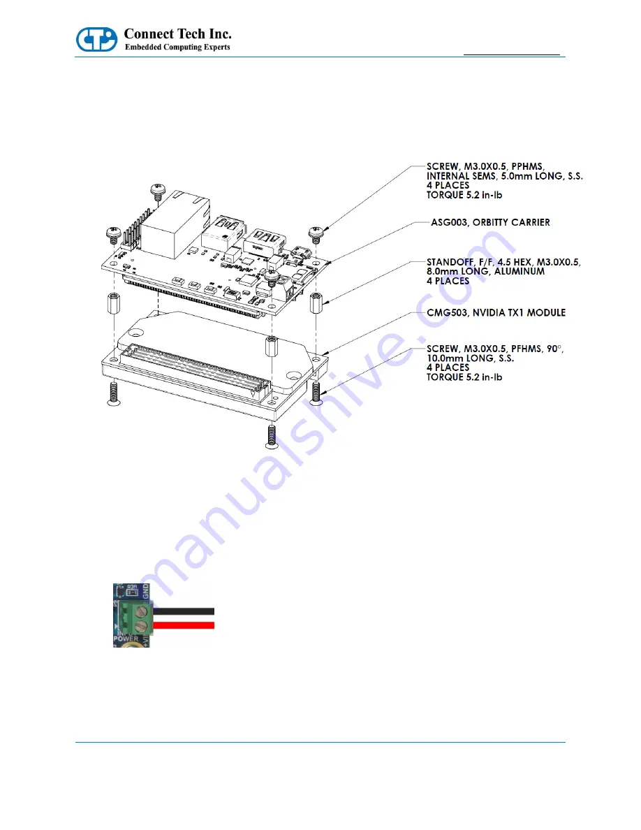
 

2.


Install the Jetson TX1 Module onto the Orbitty Carrier as shown below: 


3.


Install the necessary cables for application. At a minimum these would include: 


a)


HDMI video display cable 

b)


Keyboard and mouse via USB 

 
For additional information on the relevant cables, please see the Cables and Interconnects section of this 
manual. 
 

4.


Connect the main power input to the Wire-to-Board Screw Terminal on board as shown below: 
+9V to +15V to the +VIN terminal and Ground to the GND terminal. 


5.


Switch ON the Power Supply. DO NOT power up your system by plugging in live power. 


Summary of Contents for Orbitty Carrier

Page 1: ...Guide Connect Tech Inc Tel 519 836 1291 42 Arrow Road Toll 800 426 8979 North America only Guelph Ontario Fax 519 836 4878 N1K 1S6 Email sales connecttech com www connecttech com support connecttech com CTIM 00471 Revision 0 05 2016 12 01 ...

Page 2: ...Summary 9 Switch Summary Locations 9 Detailed Feature Description 10 Jetson TX1 Board to Board Connector 10 System Expansion IO Connector 11 System Expansion IO Connector Detailed Signal Descriptions 12 HDMI Connector 13 10 100 1000 Ethernet GBE 14 USB 3 0 15 USB OTG 16 USB OTG Host Mode 16 USB OTG Client Mode Used for Image Flashing 16 Input Power 17 Input Power Wiring 17 Switch Details 18 DIP Sw...

Page 3: ...de www connecttech com Document CTIM 00471 Revision 0 05 Page 3 of 27 Connect Tech Inc 800 426 8979 519 836 1291 Date 2016 12 01 Thermal Details 25 Mechanical Details 26 3D STEP Model 26 2D Dimensions Drawing 26 Stack up Drawing 27 Cables 27 ...

Page 4: ...ou Our support section is available 24 hours a day 7 days a week on our website at www connecttech com sub support support asp See the contact information section below for more information on how to contact us directly Our technical support is always free Contact Information Mail Courier Connect Tech Inc Technical Support 42 Arrow Road Guelph Ontario Canada N1K 1S6 Email Internet sales connecttec...

Page 5: ...ilable Should the product prove to be irreparable Connect Tech Inc reserves the right to substitute an equivalent product if available or to retract the Warranty if no replacement is available The above warranty is the only warranty authorized by Connect Tech Inc Under no circumstances will Connect Tech Inc be liable in any way for any damages including any lost profits lost savings or other incid...

Page 6: ...ng a grounded wrist strap when handling circuit boards at a minimum you should touch a grounded metal object to dissipate any static charge that may be present on you Only handling circuit boards in ESD safe areas which may include ESD floor and table mats wrist strap stations and ESD safe lab coats Avoiding handling circuit boards in carpeted areas Try to handle the board by the edges avoiding co...

Page 7: ... 10 100 1000 BASE T USB 1x USB 3 0 5Gbps 1A Maximum Current Sourcing 1x USB 2 0 w OTG functionality Audio Output HDMI Integrated UART 2x 3 3V UART Ports TX RX lines only GPIO 4 bits GPIO 3 3V CMOS Level Configurable as inputs or outputs SD Card 1x microSD Card Slot 4 bit Data Support for SD 4 0 Specification without UHS II Video Inputs Video Inputs can be accessed through any of the of the followi...

Page 8: ... Connect Tech Inc 800 426 8979 519 836 1291 Date 2016 12 01 Product Overview Block Diagram Connector Locations Top Side FAN SYS PWR SWITCH S1 POWER BUTTON SW1 RESET BUTTON SW3 RECOVERY BUTTON SW2 POWER INPUT P9 MICRO SD P6 SYS LED PWR LED Gigabit Ethernet P6 USB 3 0 P7 USB OTG P8 HDMI P2 EXPANSION IO HEADER P4 ...

Page 9: ...all Misc IO P5 Gigabit Ethernet Gigabit Ethernet 10 100 1000 BASE T Connection P6 Micro SD Card Slot Micro SD Card Slot 4 bit Data Support for SD 4 0 P7 USB 3 0 USB 3 0 Type A Host Connection P8 USB OTG USB OTG Host Mode and Client Mode capable P9 Power Input DC Power Input 9V to 15V Switch Summary Locations Designator Function Description S1 Fan Power Control Power Start up Control FAN PWM Always...

Page 10: ...1 Module This connects to the Orbitty Carrier via a Samtec SEARAY Board to Board Connector Function NVIDIA Jetson TX1 Interface Location P1 Type Samtec SEARAY Connector Carrier Connector Part Number SEAM 50 03 5 S 08 2 A K Manufacturer Samtec Mating Connector Part Number SEAF 50 05 S 08 02 A K Manufacturer Samtec Pinout Refer to NVIDIA s Jetson TX1 System on Module datasheet for pinout details Boa...

Page 11: ...tons The System Expansion IO Connector also has 2 voltage output pins to allow powering of external devices Function System Connector Location P4 Type 0 1 2 54mm Pitch IDC Header DIL Carrier Connector Part Number TSW 110 07 L D Manufacturer Samtec Mating Connector Any IDC DIC 0 1 Cable Socket or Jumper Wire Assemblies Cable CBG116 Pinout Pin Description Pin Description 1 3 3V OUTPUT 2 5V OUTPUT 3 ...

Page 12: ...l show up as dev ttyS0 Input 3 3V CMOS 4 UART1 TX UART 1 Transmit Pin This signal is the UART channel 1 output from the TX1 Module This is level shifted on the Orbitty carrier to support 3 3V logic Under L4T this port will show up as dev ttyTHS2 Output 3 3V CMOS 5 UART1 RX UART 1 Receive Pin This signal is the UART channel 1 input on TX1 Module This is level shifted on the Orbitty carrier to suppo...

Page 13: ...l Power Button Source Pulse Short this signal to GND to initiate a power sequence Input 17 GND Ground Reference Connection This pin is connected to the Orbitty Carrier s main digital ground connection Use this pin as a reference return for any externally connected peripherals to the Expansion IO Connector Reference 16 18 19 20 HDMI Connector Function HDMI Connector Location P2 Type HDMI Type A Con...

Page 14: ...ase note that Fan PWM speed control is NOT natively supported by the stock L4T builds If users wish to use the native builds you must enable the S1 DIP Switch to put the Fan into the Always ON mode To enable PWM functionality speed control users must deploy CTI L4T BSP and enable the S1 DIP Switch to put the Fan into the PWM Enabled mode 10 100 1000 Ethernet GBE Function Gigabit Ethernet Connector...

Page 15: ...O_CD USB 3 0 The Orbitty Carrier provides one external USB 3 0 Port with an integrated USB 2 0 Port The USB 3 0 signals are sourced directly from the Jetson TX1 Module Over current protection power supply filtering and ESD protection is provided on board The current limit on this port is set to 1A if more current capacity is required please contact sales connecttech com Function USB 3 0 Location P...

Page 16: ...Pi n Description 1 VBUS 2 USB 2 0 D 3 USB 2 0 D 4 USB ID 5 GND USB OTG Host Mode To put the USB OTG port into HOST mode the USB ID pin needs to be left floating Most USB Micro A to Type A Female cables will do this internally USB OTG Client Mode Used for Image Flashing To put the USB OTG port into CLIENT mode the USB ID pin needs to be tied to GND Most USB Micro B cables will do this internally On...

Page 17: ...ingle power input to power all on board devices A power input range of 9V to 15V is recommended Function Input Power Location P9 Type 3 5mm Pitch Wire to Board Screw Terminal P N TBD Mating N A Any Stripped and Tinned 8 22 AWG Wire Cable N A Pinout Pin Description 1 VIN 2 GND Input Power Wiring The positive wire should be connected to the VIN terminal and the negative wire should be connected to t...

Page 18: ...ls DIP Switch Details S1 The Orbitty Carrier has a 2 position DIP switch block which controls the PWM Fan Control and the main Power up Start up Control Position No Position Description Switch ON Switch OFF 1 PWMFan Control FAN PWMEnabled SW Controlled FAN Always ON 2 Power Up Start up Control AT Mode Automatic Start up Enabled ATX Mode Power Button Press Required S1 Usage Examples ...

Page 19: ...in ATX Mode a button press will initiate boot up sequence When Orbitty is ON a button press will initiate a power down sequence in the Operating System When Orbitty is ON and button is held for 5 seconds the system will do a hard power off power down ungracefully SW3 Reset Button When button is pressed the system will initiate a Reset sequence SW2 Recovery Button Use this button to perform the For...

Page 20: ...r as shown below 3 Install the necessary cables for application At a minimum these would include a HDMI video display cable b Keyboard and mouse via USB For additional information on the relevant cables please see the Cables and Interconnects section of this manual 4 Connect the main power input to the Wire to Board Screw Terminal on board as shown below 9V to 15V to the VIN terminal and Ground to...

Page 21: ...is supplied by a standard AC line cord and has a cable length of approximately 1 5m Contact our sales department about the MSG064 for more details On Board Indicator LED s The Orbitty Carrier has 2 on board indicator LEDs LED Designator Description D11 Power Good Indicator If this LED is ON this indicates that all on board power supplies are ON and at the proper level D2 System Status Indicator If...

Page 22: ...led Please refer to the module manufacturer s manual for full details on the current consumption of the particular module you are using All measurements below are used with 12V applied to the Input Power Connector Actual Measurements Amps Watts Orbitty Carrier standalone no module installed powered ON with no loads 0 03 0 36 Module Installed Ubuntu in headless mode remote operation over serial con...

Page 23: ...tPack includes host and target development tools APIs and packages OS images tools APIs middleware samples documentation including compiling samples to enable developers to jump start their development environment for developing with the Jetson Embedded Platform The latest release of JetPack runs on an Ubuntu 14 04 Linux 64 bit host system and supports both the latest Jetson TX1 Development Kit an...

Page 24: ...CTING THE INPUT POWER SUPPLY Connecting a device while powered on may damage the Orbitty Carrier or peripheral device Procedure to place system in Force USB Recovery Mode 1 Power OFF the Orbitty The Orbitty MUST be powered OFF and not in a suspend or sleep state 2 Use a USB Micro B to USB Type A Cable Plug the Micro B end into the Orbitty USB OTG port Plug the USB Type A end into a host PC 3 Power...

Page 25: ...l Transfer Plate TTP temperatures below the specified temperatures shown in the table below under the maximum thermal load and system conditions for their use case Parameter Value Units Maximum Orbitty Carrier Operating Temperature 85 C Maximum TX1 TTP Operating Temperature 80 C Maximum TX1 CPU Operating Temperature 89 C Maximum TX1 GPU Operating Temperature 90 5 C TX1 CPU Shutdown Temperature 103...

Page 26: ...471 Revision 0 05 Page 26 of 27 Connect Tech Inc 800 426 8979 519 836 1291 Date 2016 12 01 Mechanical Details 3D STEP Model A complete 3D STEP Model file of the Orbitty Carrier can be downloaded here http www connecttech com ftp 3d_models ASG003_3D_MODEL zip 2D Dimensions Drawing ...

Page 27: ...tech com Document CTIM 00471 Revision 0 05 Page 27 of 27 Connect Tech Inc 800 426 8979 519 836 1291 Date 2016 12 01 Stack up Drawing Cables The Orbitty Carrier does not require any special external cables Standard USB HDMI and Ethernet Cabling can be used ...

Reviews: