CONCEPT
CONCEPT
CONCEPT
CONCEPT
CONCEPT. Small Low Profile P
. Small Low Profile P
. Small Low Profile P
. Small Low Profile P
. Small Low Profile Powered Enclosure.
owered Enclosure.
owered Enclosure.
owered Enclosure.
owered Enclosure.
Installation Notes.
4
Alarm Output Wiring.
LOW BATTERY & AC FAIL ALARMS.
Outputs are provided on the Power Supply for indication of Low Battery (i.e. Below
11 Volts) & AC Fail conditions. End-of-Line Resistors are already fitted on the Power Supply PCB. The outputs are wired
directly to Zone Inputs on Concept Modules as shown, and programmed appropriately.
NOTE: This wiring is not required if the Power Supply is connected to the Mini Expander via Ribbon cable, P/No: 605049 or
605050. When connected in this way, Zones 7 & 8 on the Mini Expander are connected internally to the AC fail and Low
Battery inputs and cannot be used as general purpose Zone Inputs.
GND
ZONE Input
GND
ZONE Input
GND
DET - (0V)
AUX Output
Power Supply Control Wiring
The Power Supply can be configured to allow external control of the Power Supply Regulator. When the PSDOWN input is shorted
to 0 volts the Power Supply Regulator will be disabled. This will cause the Power Supply unit to run on the Battery if present. If the
Battery level drops below 11 volts, LBATT will go into alarm.
A typical application could be Battery testing. Using any Auxiliary output from a Concept module, connect the output to PSDOWN
as shown below. When the Auxiliary is turned OFF the power supply is enabled; When the Auxiliary is turned ON the power supply
is operating from its battery only. (NOTE: This is the reverse of earlier versions with JP2 selection pins fitted)
0V
PSDOWN
LBATT
ACFAIL
TB2
Power Supply
Board
Concept Module
Zone Inputs
0V
PSDOWN
LBATT
ACFAIL
TB2
Power Supply
Board
Concept Module
Auxiliary Output
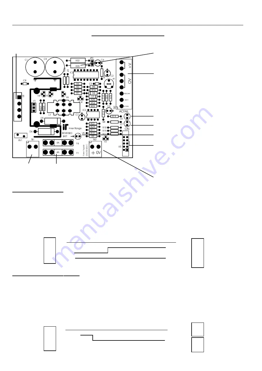
THE 2A POWER SUPPLY PCB
TB1. AC Input.
16V AC. 2.5A.
Fuses.
F1
AC Input Protection. 4A.
F4
Battery Protection. 4A.
R20
Current Limit select.
Cut R20 out to
reduce current limit to 1.0 Amp.
e.g. If using 16V 1.5A Plug pack. (P/N:560001)
TB2.
Power Supply output, Alarm outputs and
Control input.
See below for details.
INDICATOR
LEDS.
Provide visual indication of:
•
AC Fail
•
Output Present
•
Reverse Battery connection. (Fuse 4 Blown)
X3
Direct Ribbon Cable connection to
Concept Modules where facility exists.
e.g. Mini Expanders & 2 Door Access Modules.
Note: On 2 Door Access Modules this cable only
supports the +V and 0V connections.
TB3. Battery
12V. 7AH. SLA Battery connection.
B1
Rectifier. CAUTION!
Rectifier can become hot. Please exercise care.


