background image


Corporate Office: 724.584.5500 

 Instant Access 24/7 (Parts and Service): 800.458.1960 

 Parts and Service

814.437.6861 

16 

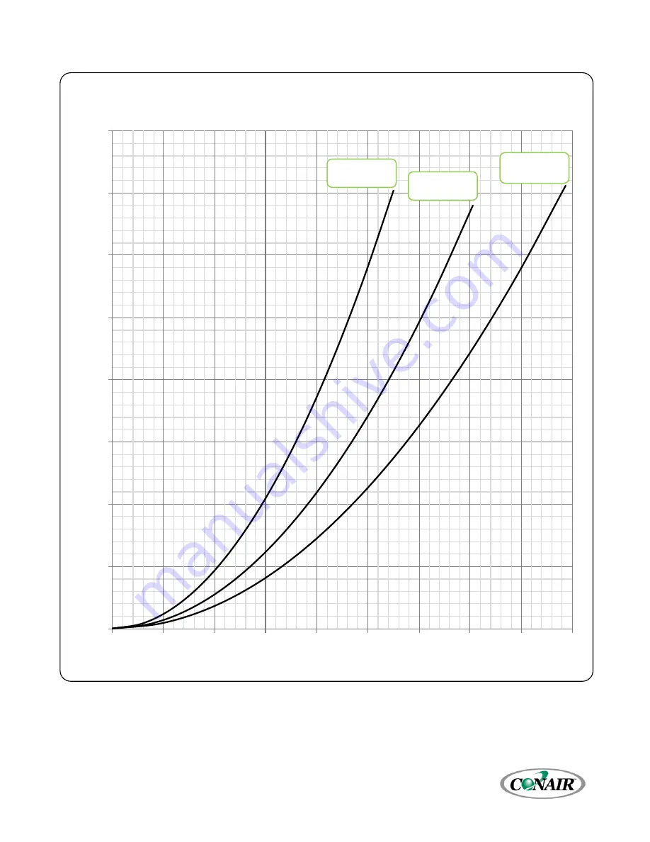
Figure 6 – High Flow Chiller Coolant Pressure Drop (30 through 50 ton Single-Circuit Chillers) 


0

5

10

15

20

25

30

35

40

0

50

100

150

200

250

300

350

400

450

Pr

ess

ur

Lo

ss (

psi

)

Flow (gpm)

High Flow Chiller Coolant Circuit Pressure Drop

(Water at 50°F)

TSEW50S 

& TSER50S

TSEW40S 

& TSER40S

TSEW30S 

& TSER30S

ESEW-030S 

ESER-030S 

ESEW-040S 

ESER-040S 

ESEW-050S 

ESER-050S 

Summary of Contents for ESEW-0100D

Page 1: ...DE UGH050 0816 Corporate Office 724 584 5500 Instant Access 24 7 Parts and Service 800 458 1960 Parts and Service 814 437 6861 www conairgroup com ESE Series Central Chillers ESE Series Scroll Central Chillers ...

Page 2: ...s lists together for documentation of your equipment Date Manual Number UGH050 0816 Serial Number s Model Number s DISCLAIMER Conair shall not be liable for errors contained in this User Guide or for incidental consequential damages in connection with the furnishing performance or use of this information Conair makes no warranty of any kind with regard to this information including but not limited...

Page 3: ...Corporate Office 724 584 5500 Instant Access 24 7 Parts and Service 800 458 1960 Parts and Service 814 437 6861 Page Intentionally Blank ...

Page 4: ... through 160 ton Dual Circuit Chillers 14 Figure 5 High Flow Chiller Coolant Circuit Pressure Drop 10 through 25 ton Single Circuit Chillers 15 Figure 6 High Flow Chiller Coolant Pressure Drop 30 through 50 ton Single Circuit Chillers 16 Figure 7 High Flow Chiller Coolant Pressure Drop 20 through 50 ton Dual Circuit Chillers 17 Figure 8 High Flow Chiller Coolant Pressure Drop 60 through 100 ton Du...

Page 5: ...Flow Pump Set 2 Electrical Data 60 Hz Error Book Table 17 ESEW ESER Dual Circuit Chiller Electrical Data 60 Hz 40 Table 18 ESEW ESER Dual Circuit Chiller with Standard Flow Pump Set Electrical Data 60 Hz 41 Table 19 ESEW ESER Dual Circuit Chiller with High Flow Pump Set 1 Electrical Data 60 Hz 42 Table 20 ESEW ESER Dual Circuit Chiller with High Flow Pump Set 2 Electrical Data 60 Hz Error Book Tab...

Page 6: ...ion Valve Setup Screen 57 Figure 38 EXV1 Expansion Valve Setup Screen 57 Table 25 EXV1 Setup Parameters 57 Menu 1 EXV2 Hot Gas Bypass Setup 58 EXV2 Hot Gas Bypass Setup Screen Optional 58 Figure 39 EXV2 Hot Gas Bypass Screen 58 Table 26 EXV2 Setup Parameters 58 Menu 1 Water Regulating Valve WRV Setup 59 WRV Water Regulating Valve Setup Screen 59 Figure 40 WRV Setup Screen 59 Table 27 WRV Setup Par...

Page 7: ...68 Figure 52 Counters 1 Screen 68 Figure 53 Counters 2 Screen 68 Figure 54 Counters 3 Screen 68 Menu 2 Overview 69 Figure 55 Menu 2 69 Table 32 Menu 2 Functions 69 Menu 2 Hardware Options Selected 70 Hardware Options Screen 70 Figure 56 Hardware Options Screen 70 Menu 2 Date Time 71 Menu 2 System Menu 71 Menu 2 Defaults 71 Figure 57 Restore Factory Settings 71 Figure 58 Factory Settings Restored 7...

Page 8: ...ck Condenser 77 Water Cooled Condenser Check 77 Remote Air Cooled Condenser Check 77 Step 4 Check Refrigerant Valves 77 Step 5 Verify Freezestat Setting 78 Step 6 Turn On Control Power 78 Step 7 Establish Coolant Flow 78 Step 8 Intial Unit Operation 78 Low Ambient Start Up Remote Condensers 78 Preventive Maintenance 79 Once a Week 79 Once a Month 80 Once Every Three Months 80 Once a Year 80 Cleani...

Page 9: ...Corporate Office 724 584 5500 Instant Access 24 7 Parts and Service 800 458 1960 Parts and Service 814 437 6861 Page Intentionally Blank ...

Page 10: ...d other local laws pertaining to the use and operation of this equipment we do not reference them in this manual There is no substitute for common sense and good operating practices when placing any mechanical equipment into operation We encourage all personnel to familiarize themselves with this manual s contents Failure to do so may unnecessarily prolong equipment down time The chiller uses chem...

Page 11: ... and cause suffocation WARNING This equipment contains hazardous voltages that can cause severe injury or death WARNING This equipment contains refrigerant under pressure Accidental release of refrigerant under pressure can cause personal injury and or property damage WARNING This equipment may contain fan blades or other sharp edges Make sure all fan guards and other protective shields are secure...

Page 12: ...dels Process Chiller 5D 1 5A 5D 1 5A 5D 1 5A 5D 1 5A 7 5D 2A 10D 2A 10D 3A 10D 3A 15D 3A Process Connection Size inch 1 1 2 2 2 2 3 3 4 D Length inches mm 84 2134 84 2134 84 2134 96 2438 96 2438 96 2438 96 2438 108 2743 108 2743 E Width inches mm 72 1829 72 1829 76 1930 76 1930 76 1930 92 2337 92 2337 95 2413 100 2540 F Height inches mm 75 1905 75 1905 75 1905 75 1905 75 1905 75 1905 75 1905 75 19...

Page 13: ...25D 10E Process Connection Size inch 2 2 2 3 3 4 4 4 6 D Length inches mm 108 2743 108 2743 108 2743 120 3048 132 3353 132 3353 132 3353 144 3658 144 3658 E Width inches mm 78 1981 78 1981 78 1981 90 2286 90 2286 1053 26746 1103 28016 1103 28016 1103 28016 F Height inches mm 75 1905 75 1905 75 1905 75 1905 75 1905 75 1905 75 1905 75 1905 90 2286 Ship Weight lbs kg 4100 1860 4300 1950 4400 1996 470...

Page 14: ...5 1041 275 1041 450 1703 450 1703 Pump Models Process Chiller 5D 1 5A 5D 1 5A 5D 1 5A 5D 1 5A 7 5D 2A 10D 2A 10D 3A 10D 3A 15D 3A Process Connection Size inch 1 1 2 2 2 2 3 3 4 D Length inches mm 84 2134 84 2134 84 2134 96 2438 96 2438 96 2438 96 2438 108 2743 108 2743 E Width inches mm 64 1626 64 1626 64 1626 76 1930 76 1930 92 2337 92 2337 96 2438 98 2489 F Height inches mm 75 1905 75 1905 75 19...

Page 15: ... 2650 700 2650 1000 3785 Pump Models Process Chiller 5D 1 5A 7 5D 2A 10D 2A 10D 3A 10D 3A 15D 3A 15D 5A 20D 7 5F 20D 10E Process Connection Size inch 2 2 2 3 3 4 4 4 6 D Length inches mm 108 2743 108 2743 108 2743 120 3048 132 3353 132 3353 132 3353 144 3658 144 3658 E Width inches mm 74 1880 74 1880 74 1880 74 1880 74 1880 92 2337 102 2591 102 2591 102 2591 F Height inches mm 75 1905 75 1905 75 1...

Page 16: ...50S 223 5664 45 1143 54 1372 1475 669 42 400 65 16 0 2 2 KCL095 ESER 060S 278 7061 45 1143 54 1372 1950 885 51 800 66 16 0 3 2 KCL110 ESER 080S 333 8458 45 1143 54 1372 2300 1043 62 100 67 21 0 3 2 Dual Circuit KCM034 ESER 020D 83 2108 83 2108 48 1219 830 376 28 400 55 4 9 1 1 KCL047 ESER 030D 113 2870 87 2210 54 1372 1275 578 47 900 65 16 0 2 1 KCL060 ESER 040D 113 2870 87 2210 54 1372 1350 612 4...

Page 17: ... equipment damage while the equipment is still partially packed will help in this regard Refrigerant lines can be susceptible to damage in transit Check for broken lines oil leaks damaged controls or any other major component torn loose from its mounting point Record any signs of concealed damage and file a shipping damage claim immediately with the shipping company Most carriers require concealed...

Page 18: ...oper rigging methods to prevent damage to components Avoid impact loading caused by sudden jerking when lifting or lowering the chiller Use pads where abrasive surface contact may occur Use the frame supporting the unit for positioning it with a crane or a forklift Chilled Water Piping Proper insulation of chilled water piping is crucial to prevent condensation The formation of condensation on chi...

Page 19: ... preventive maintenance and in troubleshooting the chiller performance Master Temperature Sensor This section only applies to installations where multiple chillers are in a common system where one chiller will be the master with the other chillers serving as slaves In those situations a field installed master fluid temperature sensor is required to be field installed in the common chilled water su...

Page 20: ...Drop 10 through 30 Ton Single Circuit Chillers 0 5 10 15 20 25 30 35 40 0 20 40 60 80 100 120 140 160 Pressure Loss psi Flow gpm Standard Flow Chiller Coolant Circuit PressureDrop Water at 50 F TSEW15S TSER15S TSEW20S TSER20S TSEW25S TSER25S TSEW30S TSER30S TSEW10S TSER10S ESEW 015S ESER 015S ESEW 010S ESER 010S ESEW 020S ESER 020S ESEW 025S ESER 025S ESEW 030S ESER 030S ...

Page 21: ...ircuit Pressure Drop 40 through 80 Ton Single Circuit Chillers 0 5 10 15 20 25 30 35 40 0 50 100 150 200 250 300 350 400 Pressure Loss psi Flow gpm Standard Flow Chiller Coolant Circuit PressureDrop Water at 50 F TSEW50S TSER50S TSEW60S TSER60S TSEW80S TSER80S TSEW40S TSER40S ESEW 040S ESER 040S ESEW 050S ESER 050S ESEW 060S ESER 060S ESEW 080S ESER 080S ...

Page 22: ...rop 20 through 160 ton Dual Circuit Chillers 0 5 10 15 20 25 30 35 40 0 40 80 120 160 200 240 280 320 Pressure Loss psi Flow gpm Standard Flow Chiller Coolant Circuit PressureDrop Water at 50 F TSEW30D TSER30D TSEW40D TSER40D TSEW50D TSER50D TSEW60D TSER60D TSEW20D TSER20D ESEW 020D ESER 020D ESEW 030D ESER 030D ESEW 040D ESER 040D ESEW 050D ESER 050D ESEW 060D ESER 060D ...

Page 23: ... Pressure Drop 80 through 160 ton Dual Circuit Chillers 0 5 10 15 20 25 30 35 40 0 100 200 300 400 500 600 700 800 Pressure Loss psi Flow gpm Standard Flow Chiller Coolant Circuit PressureDrop Water at 50 F TSEW100D TSER100D TSEW120D TSER120D TSEW160D TSER160D TSEW80D TSER80D ESEW 080D ESER 080D ESEW 0100D ESER 0100D ESEW 0120D ESER 0120D ESEW 0160D ESER 0160D ...

Page 24: ...Pressure Drop 10 through 25 ton Single Circuit Chillers 0 5 10 15 20 25 30 35 40 0 20 40 60 80 100 120 140 160 180 200 220 240 Pressure Loss psi Flow gpm High Flow Chiller Coolant Circuit Pressure Drop Water at 50 F TSEW15S TSER15S TSEW20S TSER20S TSEW25S TSER25S TSEW10S TSER10S ESEW 010S ESER 010S ESEW 015S ESER 015S ESEW 020S ESER 020S ESEW 025S ESER 025S ...

Page 25: ...ow Chiller Coolant Pressure Drop 30 through 50 ton Single Circuit Chillers 0 5 10 15 20 25 30 35 40 0 50 100 150 200 250 300 350 400 450 Pressure Loss psi Flow gpm High Flow Chiller Coolant Circuit Pressure Drop Water at 50 F TSEW50S TSER50S TSEW40S TSER40S TSEW30S TSER30S ESEW 030S ESER 030S ESEW 040S ESER 040S ESEW 050S ESER 050S ...

Page 26: ...Pressure Drop 20 through 50 ton Dual Circuit Chillers 0 5 10 15 20 25 30 35 40 0 50 100 150 200 250 300 350 400 450 500 Pressure Loss psi Flow gpm High Flow Chiller Coolant Circuit Pressure Drop Water at 50 F TSEW30D TSER30D TSEW40D TSER40D TSEW50D TSER50D TSEW20D TSER20D ESEW 020D ESER 020D ESEW 030D ESER 030D ESEW 040D ESER 040D ESEW 050D ESER 050D ...

Page 27: ... Chiller Coolant Pressure Drop 60 through 100 ton Dual Circuit Chillers 0 5 10 15 20 25 30 35 40 0 100 200 300 400 500 600 700 800 900 Pressure Loss psi Flow gpm High Flow Chiller Coolant Circuit Pressure Drop Water at 50 F TSEW100D TSER100D TSEW80D TSER80D TSEW60D TSER60D ESEW 060D ESER 060D ESEW 080D ESER 080D ESEW 0100D ESER 0100D ...

Page 28: ...ter Circuit Pressure Drop 10 through 30 ton Single Circuit Chillers 0 3 6 9 12 15 18 21 24 0 25 50 75 100 125 150 175 200 Pressure Loss psi Flow gpm Condenser Water Circuit Pressure Drop Water at 85 F with Condenser Water Regulating Valve 100 Open TSEW10S TSEW15S TSEW20S TSEW25S TSEW30S ESEW 010S ESEW 015S ESEW 020S ESEW 025S ESEW 030S ...

Page 29: ...ser Water Circuit Pressure Drop 40 through 80 ton Single Circuit Chillers 0 3 6 9 12 15 18 21 24 0 50 100 150 200 250 300 350 400 450 500 Pressure Loss psi Flow gpm Condenser Water Cicuit PressureDrop Water at 85 F with Condenser Water Regulating Valve 100 Open TSEW40S TSEW50S TSEW60S TSEW80S ESEW 040S ESEW 050S ESEW 060S ESEW 080S ...

Page 30: ...ater Circuit Pressure Drop 20 through 60 ton Dual Circuit Chillers 0 3 6 9 12 15 18 21 24 0 50 100 150 200 250 300 350 400 Pressure Loss psi Flow gpm Condenser Water Circuit Pressure Drop Water at 85 F with Condenser Water Regulating Valve 100 Open TSEW20D TSEW30D TSEW40D TSEW50D TSEW60D ESEW 020D ESEW 030D ESEW 040D ESEW 050D ESEW 060D ...

Page 31: ...ater Circuit Pressure Drop 80 through 160 ton Dual Circuit Chillers 0 3 6 9 12 15 18 21 24 0 100 200 300 400 500 600 700 800 900 1000 Pressure Loss psi Flow gpm Condenser Water Circuit Pressure Drop Water at 85 F with Condenser Water Regulating valve 100 Open TSEW80D TSEW100D TSEW120D TSEW160D ESEW 080D ESEW 0100D ESEW 0120D ESEW 0160D ...

Page 32: ...r chimneys Fasten the mounting legs at their base to the steel or concrete of the supporting structure For units mounted on a roof structure the steel support base holding the condenser should be elevated above the roof and attached to the building Avoid areas that can create a micro climate such as an alcove with east north and west walls that can be significantly warmer than surrounding areas Th...

Page 33: ...hipping dimensions and provide more protection to the coil from possible damaged caused by impact loading over rough roads and transit conditions Follow the below for mounting of the legs and lifting into position Use only qualified persons using the proper equipment when lifting and positioning the condenser Lifting brackets or holes are at the corners for attaching lifting slings Use spreader ba...

Page 34: ...duce shipping dimensions and provide more protection to the coil from possible damaged caused by impact loading over rough roads and transit conditions Follow the below for mounting of the legs and lifting into position Use only qualified persons using the proper equipment when lifting and positioning the condenser Lifting brackets or holes are at the corners for attaching lifting slings Use sprea...

Page 35: ...nd flow dry nitrogen through the system This prevents the formation of toxic gases corrosive acids and the formation of scale within the copper tube Note Do not use soft solders For copper to copper joints use a copper phosphorus braze alloy BCuP per the American Welding Society with 5 BCuP 3 to 15 BCuP 5 silver content Only use a high silver content brazing alloy BAg per AWS for copper to brass o...

Page 36: ...Service 814 437 6861 27 Figure 13 Condenser Located with No Elevation Difference Figure 14 Condenser Located above Chiller Unit Condenser Width To be same as condenser width Chiller 15 minimum at liquid exit from condenser W W Chiller Locate condenser so condenser liquid turns down right away ...

Page 37: ...ngth is the approximate friction loss from the combined linear run of pipe and the equivalent feet of elbows valves and other components in the refrigeration piping The sum total is the equivalent length of pipe that would have the same pressure loss See the ASHRAE Refrigeration Handbook for more information Follow these steps when calculating line size 1 Start with an initial approximation of equ...

Page 38: ...charge The total length between the chiller unit and the air cooled condenser must not exceed 200 actual feet 70 0 m or 300 equivalent feet 91 4 m Liquid line risers in the system will require an additional 0 5 psig pressure drop per foot of vertical rise When it is necessary to have a liquid line riser make the vertical run immediately after the condenser before any additional restrictions The li...

Page 39: ... 50 50 75 75 100 100 1 125 125 1 150 150 1 175 175 1 200 200 1 225 225 1 250 250 1 275 1 275 1 300 1 300 1 20 Ton Circuit R410A 25 Ton Circuit R410A Total Equivalent Length ft Liquid Line Size Inch OD Total Equivalent Length ft Liquid Line Size Inch OD Horizontal or Downflow Upflow 1 to 5 ft Upflow 6 to 10 ft Upflow 11 to 15 ft Horizontal or Downflow Upflow 1 to 5 ft Upflow 6 to 10 ft Upflow 11 to...

Page 40: ...1 125 1 1 1 1 150 1 1 1 1 150 1 1 1 1 175 1 1 1 1 175 1 1 1 1 200 1 1 1 1 200 1 1 1 1 225 1 1 1 1 225 1 1 1 1 250 1 1 1 1 250 1 1 1 2 275 1 1 1 1 275 1 1 1 2 300 1 1 1 1 300 1 1 1 2 50 Ton Circuit R410A 60 Ton Circuit R410A Total Equivalent Length ft Liquid Line Size Inch OD Total Equivalent Length ft Liquid Line Size Inch OD Horizontal or Downflow Upflow 1 to 5 ft Upflow 6 to 10 ft Upflow 11 to 1...

Page 41: ...e hot gas flow at the rate of inch per each 10 foot 1 27 cm per 3 05 m of horizontal run If the chiller unit is below the condenser loop the discharge line to at least 1 inch 2 54 cm above the top of the condenser Install a pressure tap valve at the condenser to facilitate measuring pressure for service Take careful consideration in the design of the discharge gas riser Figure 16 Vertical Riser Tr...

Page 42: ...ize lines using the ASHRAE Refrigeration Handbook or other suitable design guide Table 8 Discharge Line Sizes for Chiller inches OD Circuit Tons Total Equivalent Length ft 25 50 75 100 125 150 175 200 225 250 275 300 10 1 1 1 1 1 15 1 1 1 1 1 1 1 1 1 1 20 1 1 1 1 1 1 1 1 1 1 1 25 1 1 1 1 1 1 1 1 1 1 1 1 30 1 1 1 1 1 1 1 1 1 1 1 1 40 1 1 1 1 1 1 2 2 2 2 2 2 50 1 1 1 1 1 2 2 2 2 2 2 2 60 1 1 1 2 2 2...

Page 43: ... A A A A A A A A A B 1 B 1 B 1 B 1 B 1 B 1 B 1 B 1 B 2 B 2 B 2 B 2 Calculating System Refrigerant and Oil Charge To determine the approximate charge first refer to Table 10 and establish the required charge for the condenser and chiller Values given in Table 10 are per circuit Then refer to Table 11 to determine the charge required for the field installed piping per circuit The approximate charge ...

Page 44: ... of condenser fans present there will be different fan cycling pressure control setting requirements It is important that these settings be correct in order to maintain proper capacity control and operation of the system Each refrigerant circuit has a separate head pressure control circuit Refer to Table 12 for the proper pressure settings Table 12 Condenser Fan Pressure Settings psig Stage Number...

Page 45: ... leads on the line power terminal blocks or the unit mounted disconnect Do not interchange any load leads that are from the unit contactors or the motor terminals WARNING This equipment contains hazardous voltages that can cause severe injury or death WARNING This equipment contains refrigerant under pressure Accidental release of refrigerant under pressure can cause personal injury and or propert...

Page 46: ...460 414 508 2 23 1 150 53 80 575 518 632 2 19 9 109 46 70 ESEW 030S ESER 030S 208 187 253 2 55 8 340 127 200 230 187 253 2 55 8 340 127 200 460 414 508 2 26 9 173 62 100 575 518 632 2 23 7 132 55 80 ESEW 040S ESER 040S 208 187 253 2 72 4 538 164 250 230 187 253 2 72 4 538 164 250 460 414 508 2 30 8 229 71 110 575 518 632 2 25 0 180 58 90 ESEW 050S ESER 050S 208 187 253 2 85 3 605 193 300 230 187 2...

Page 47: ...4 62 80 575 518 632 2 19 9 109 1 6 0 1 1 9 53 70 ESEW 030S ESER 030S 208 187 253 2 55 8 340 1 24 3 1 6 6 157 200 230 187 253 2 55 8 340 1 22 0 1 6 0 154 200 460 414 508 2 26 9 173 1 11 0 1 3 0 75 100 575 518 632 2 23 7 132 1 8 8 1 2 4 65 80 ESEW 040S ESER 040S 208 187 253 2 72 4 538 1 31 0 1 6 6 200 250 230 187 253 2 72 4 538 1 28 0 1 6 0 197 250 460 414 508 2 30 8 229 1 14 0 1 3 0 86 110 575 518 ...

Page 48: ... 4 68 90 575 518 632 2 19 9 109 1 11 2 1 1 9 58 70 ESEW 030S ESER 030S 208 187 253 2 55 8 340 1 31 0 1 6 6 163 200 230 187 253 2 55 8 340 1 28 0 1 6 0 160 200 460 414 508 2 26 9 173 1 14 0 1 3 0 78 100 575 518 632 2 23 7 132 1 11 2 1 2 4 67 90 ESEW 040S ESER 040S 208 187 253 2 72 4 538 1 42 0 1 6 6 212 250 230 187 253 2 72 4 538 1 38 0 1 6 0 207 250 460 414 508 2 30 8 229 1 19 0 1 3 0 91 110 575 5...

Page 49: ...4 508 4 23 1 150 99 110 575 518 632 4 19 9 109 85 100 ESEW 060D ESER 060D 208 187 253 4 55 8 340 238 250 230 187 253 4 55 8 340 238 250 460 414 508 4 26 9 173 115 125 575 518 632 4 23 7 132 101 110 ESEW 080D ESER 080D 208 187 253 4 72 4 538 308 350 230 187 253 4 72 4 538 308 350 460 414 508 4 30 8 229 131 150 575 518 632 4 25 0 180 107 125 ESEW 0100D ESER 0100D 208 187 253 4 85 3 605 363 400 230 1...

Page 50: ...125 575 518 632 4 19 9 109 1 11 0 1 3 9 99 110 ESEW 060D ESER 060D 208 187 253 4 55 8 340 1 31 0 1 10 0 278 300 230 187 253 4 55 8 340 1 28 0 1 9 0 274 300 460 414 508 4 26 9 173 1 14 0 1 4 5 133 150 575 518 632 4 23 7 132 1 11 2 1 3 6 116 125 ESEW 080D ESER 080D 208 187 253 4 72 4 538 1 42 0 1 10 0 360 400 230 187 253 4 72 4 538 1 38 0 1 9 0 355 400 460 414 508 4 30 8 229 1 19 0 1 4 5 154 175 575...

Page 51: ...75 518 632 4 19 9 109 1 11 0 1 3 9 99 110 ESEW 060D ESER 060D 208 187 253 4 55 8 340 1 57 5 1 10 0 305 350 230 187 253 4 55 8 340 1 52 0 1 9 0 298 300 460 414 508 4 26 9 173 1 26 0 1 4 5 145 150 575 518 632 4 23 7 132 1 11 0 1 4 5 116 125 ESEW 080D ESER 080D 208 187 253 4 72 4 538 1 70 8 1 10 0 388 450 230 187 253 4 72 4 538 1 64 0 1 9 0 381 450 460 414 508 4 30 8 229 1 32 0 1 4 5 168 175 575 518 ...

Page 52: ...2 3 1 6 2 7 0 15 575 518 632 1 1 4 1 2 2 5 5 0 5 6 15 KCL045 208 187 253 1 3 6 2 2 6 6 19 8 21 5 25 230 187 253 1 3 6 2 2 6 6 19 8 21 5 25 460 414 508 1 1 7 2 2 3 1 9 3 10 1 15 575 518 632 1 1 4 2 2 2 5 7 5 8 1 15 KCL056 208 187 253 1 3 6 2 2 6 6 19 8 21 5 25 230 187 253 1 3 6 2 2 6 6 19 8 21 5 25 460 414 508 1 1 7 2 2 3 1 9 3 10 1 15 575 518 632 1 1 4 2 2 2 5 7 5 8 1 15 KCL068 208 187 253 1 3 6 3...

Page 53: ... 12 4 16 0 20 575 518 632 2 1 4 2 2 2 5 10 0 10 6 15 KCL090 208 187 253 2 3 6 4 2 6 6 39 6 46 0 50 230 187 253 2 3 6 4 2 6 6 39 6 46 0 50 460 414 508 2 1 7 4 2 3 1 18 6 21 0 25 575 518 632 2 1 4 4 2 2 5 15 0 16 0 20 KCL112 208 187 253 2 3 6 4 2 6 6 39 6 46 0 50 230 187 253 2 3 6 4 2 6 6 39 6 46 0 50 460 414 508 2 1 7 4 2 3 1 18 6 21 0 25 575 518 632 2 1 4 4 2 2 5 15 0 16 0 20 KCL137 208 187 253 2 ...

Page 54: ... screen will display while the Programmable Logic Controller PLC and Human Machine Interface HMI establish communications The PLC HMI version is located in the lower right hand corner of the screen Figure 18 Start Up Splash Screen Once the control communication system has established the HMI screen automatically switches to the Home Screen as shown in Figure 19 for water cooled condenser chillers ...

Page 55: ...uired to enter a new Setpoint None Process Indicator PV The chiller can be set to control entering or leaving water temperatures A PV appears after the temperature used for temperature control As standard the systems is set for leaving water temperature control which is suitable for systems with a large system volume and a buffer tank Return water temperature control is mainly for systems with a s...

Page 56: ...E Chiller The SETPOINT and PROCESS temperatures appear in a large font easily seen from a distance providing a quick glance look to validate proper operation Figure 21 Full Screen Warnings The Warning Screen Figure 22 provides a view of any warnings that currently exist within the system Warnings that are left unresolved will typically result in a fault after some time Figure 22 Warning Screen ...

Page 57: ...tatus information for a system with integral pump controls The Pump Control Screen also provides the ability to change mode selection Figure 23 Pump Control Screen Pump VFD Control Screen Optional The Pump VFD Screen Figure 24 displays pertinent pump VFD status information for system with integral pump controls with pump VFDs The Pump VFD Screen also provides the ability to change mode selection F...

Page 58: ...is password protected The main user level password is 9999 used for gaining access to changing the main system set point and various other warning and alarm settings A few higher level areas require a high level user password that is 7720 If you are attempting to access an area where neither of these passwords is accepted you main require a technician level password For access to these areas of th...

Page 59: ... 35 Figure 36 Figure 37 EXV1 Expansion Valve Setup Electric Expansion Valve Setup Superheat Control Figure 38 EXV2 Hot Gas Bypass Setup Hot Gas Bypass Setup Load Balance Valve Optional Figure 39 Water Regulating Valve Setup Water Regulating Valve Setup Discharge Pressure Control ESEW Only Figure 40 Compressor Staging Compressor staging options and stage order setup Figure 41 Figure 42 Input Output...

Page 60: ...een to appear and will display the current faults To silence this alarm press the ALARM SILENT button If multiple alarms are active at once use the DOWN and UP buttons to view all alarms When no alarms are active the white portion of the display will be blank All alarms must be resolved and reset using the RESET ALARM button Figure 26 HMI Alarm Handler Alarm History Alarm History Figure 27 display...

Page 61: ...appear as in Figure 29 The amount of antifreeze will vary depending on the actual desired operating conditions and should be enough to provide freeze protection to temperatures 15 F 9 C colder than the coldest temperature anticipated Use only antifreeze solutions designed for heat exchanger duty Do not use automotive antifreeze due to the potential for fouling that can occur once its relatively sh...

Page 62: ...again using this button The units of measure indicated on this button are the active units Menu 1 Compressor Data Compressor Data Screen The Compressor Data Screen Figure 30 and Figure 31 is accessible directly from Menu 1 Figure 25 or by touching the requested circuit on the Home Screen Figure 19 or Figure 20 This screen provides additional information relative to the particular circuit Figure 30...

Page 63: ...e 32 Interlocks There are two active buttons on the Interlocks Screen indicated by the TOUCH text which presents an even deeper view of the interlocks The Critical Interlocks Screen Figure 33 appears by touching the critical status text on the Interlocks Screen Figure 32 A critical interlock fault will shut down the entire system and must be resolved prior to restarting the system The Refrigeratio...

Page 64: ...Corporate Office 724 584 5500 Instant Access 24 7 Parts and Service 800 458 1960 Parts and Service 814 437 6861 55 Figure 33 Critical Interlocks Figure 34 Refrigeration Interlocks ...

Page 65: ...s RTU capability It also displays the current Modbus data and its associated Modbus registers as shown in the following figures Default Modbus Settings Baud 19200 Data Length 8 Parity Odd Stop Bits 1 The display of the Modbus data makes it quick and easy to verify data points between the chiller and the system to which it is connected Figure 35 Modbus Setup Screen Figure 36 Modbus Word Data Screen...

Page 66: ...at the startup percent open position 30 sec Superheat Setpoint Superheat Mode The valve meters the amount of refrigerant into the evaporator in the precise quantity in order to maintain superheat The difference between the saturated suction temperature and the suction line temperature is the superheat The superheat is factory set for 10 F and should never exceed 15 F or go below 4 F Only a trained...

Page 67: ...zero output AUTO LAST COMP ONLY The valve will only respond relative to the demand PID when operating with the last compressor running AUTO ALWAYS ON The valve will always respond relative to the demand PID regardless of how many compressors are running MANUAL MODE The manual mode value percent will be the output to the valve AUTO ALWAYS ON Minimum Position The minimum percent the valve will go to...

Page 68: ...ure 40 WRV Setup Screen Table 27 WRV Setup Parameters Menu Item Description Default Value Mode In Auto Mode the control system adjusts the valve for optimum performance In manual mode the manual mode value is the output to the valve at all times AUTOMATIC Discharge Setpoint Discharge Setpoint Value 340 PSIG Low Temp Setpoint Low temp setpoint relating to low percent setpoint During the start seque...

Page 69: ...de Value relative to available compressors AUTOMATIC Stage to Stage Delay This is the minimum delay duration between stages on multiple compressors This time delay temporarily halts the demand percent from calculating allowing the newly staged compressor to properly influence the system 60 Kp Proportional PID value 3 Ti Integral PID value 1000 Td Derivative PID value 0 Destage ΔT This is the diffe...

Page 70: ...ecreases compressors will de stage trying to maintain process setpoint If the process value reaches the stage off value then all compressors will de stage The system demand is calculated by dividing the number of active compressors by the total number of compressors available Figure 42 Compressor Staging Graph Screen Table 29 Compressor Staging Graph Parameters Menu Item Description Default Value ...

Page 71: ...ble 30 Compressor Staging Local Parameters Menu Item Description Default Value Manual Trigger Manual Trigger will immediately recalculate the stage order instead of waiting for the automatic trigger to occur None Manual OFF ON Allows the ability to manually activate a compressor for testing purposes OFF Stage Mode Automatic calculates the stage order by the AUTO STAGE HOURS parameter Manual Manual...

Page 72: ...outputs X s are discrete inputs and Y s are discrete outputs When the PLC input LED is illuminated ON the corresponding input or output is on The inputs and outputs numbers are hex base numbering system The following screens show a full complement of inputs and outputs Note Your screen may differ depending on machine type and options Figure 44 Digital Inputs Screen Figure 45 Digital Outputs Screen...

Page 73: ...mperature Offset Adjustment The Entering Water RTD and LWT Manifold RTD Dual Circuits or Master Slave Systems only are adjustable To change enter a temperature offset into the RTD Temperature Offset Screen Only change the offset if there is a discrepancy between the sensor reading and the actual temperature Figure 48 RTD Temperature Offsets Screen ...

Page 74: ...ter Control or Entering Water Control To make a change from the current selection simply press the mode of operation button This will toggle between the two options Master Only If an external leaving water temperature is used the RTD sensors must be enabled Typically a Manifold RTD temperature sensor is used when a combination leaving water temperature is being controlled i e Master Slave or Dual ...

Page 75: ... enable of the pumps AUTOMATIC Recirc On Delay Delay duration before the Recirc Pump starts 3 sec Recirc Off Delay Delay duration before stopping the Recirc Pump after initiation of a system stop 60 sec Process On Delay Delay duration before the Process Pump starts 30 sec Process Off Delay Delay duration before stopping the Process Pump after initiation of a system stop 120 sec VFD Pressure Setpoi...

Page 76: ...uts The tank ENABLE DISABLE option is located in the lower right hand corner of the screen Touch this button to toggle its state If the tank mid high sensors are enabled their status will be indicated If the mid level sensor has been off for over 10 seconds that tank water makeup valve will energize Once the high level water level sensor has activated the water makeup valve will de energize Figure...

Page 77: ...ol system keeps track of certain inputs and outputs Every time an input or output is activated a counter will record this state change This is useful in troubleshooting the system Also recorded are minimum and maximum pressure levels Once the system is powered down these counters will reset Figure 52 Counters 1 Screen Figure 53 Counters 2 Screen Figure 54 Counters 3 Screen ...

Page 78: ...nown setting occurred and the system now behaves unexpectedly Figure 57 Figure 58 System Selection Water or air cooled system selection N A Single Dual System Selection Single or dual circuit system selection N A Remote Setpoint Setup Configuration of analog Input used for system setpoint Figure 59 Remove SD Storage Used to properly close the trend file for SD removal Press this button prior to re...

Page 79: ...vice 814 437 6861 70 Menu 2 Hardware Options Selected Hardware Options Screen The Hardware Options Screen Figure 56 shows an overall status view of the current hardware options enabled This is a read only screen Make all adjustments on their appropriate screens Figure 56 Hardware Options Screen ...

Page 80: ...y impair proper functioning of the system This menu is for use only by qualified service technicians Please contact our Customer Service Department for assistance as needed to access this area of the system program Menu 2 Defaults WARNING The Default Settings screen provides the ability to restore the control system back to factory defaults in the case that an unknown setting modification occurred...

Page 81: ...igure 58 Factory Settings Restored Menu 2 Remote Setpoint Setup When the remote setpoint option is enabled an incoming 4 20mA signal controls the setpoint of the master chiller The 4 20mA signal will span from the MINIMUM SETPOINT to the MAXIMUM SETPOINT as defined in Figure 59 Figure 59 Remote Setpoint Setup Screen ...

Page 82: ...tory When active the controller requires a SD storage card be present at time of start up and will not allow the chiller to start if not present If you need to activate this feature please contact our Customer Service Department for assistance Menu 2 Trending The trending screen Figure 60 displays the setpoint temperature process temperature expansion valve and optional hot gas bypass valve if pre...

Page 83: ...LC Link Master Slave Setup Screen This screen can enable or disable the Master Slave Capability It also displays the current linked data Each chiller is capable of being a Master or a Slave To do this toggle the MASTER MODE to SLAVE MODE Figure 61 PLC Link Setup Screen Figure 62 PLC Link Word Data Screen Figure 63 PLC Link Bit Data Screen ...

Page 84: ...d circuit components can be very hot and can cause burns if touched with unprotected hands CAUTION Disconnect and lock out incoming power before installing servicing or maintaining the equipment Connecting power to the main terminal block energizes the entire electric circuitry of the unit A power supply provides 24 VDC control power Electric power at the main disconnect should be shut off before ...

Page 85: ...e is required for continuous plant productivity Unwanted Side Effects of Improper Water Quality Corrosion Scale Fouling Biological Contamination Cooling Water Chemistry Properties Electrical Conductivity pH Alkalinity Total Hardness Dissolved gases Some of the water chemistry properties can combine to cause the unwanted side effects Some of the levels are temperature dependent i e dissolved gases ...

Page 86: ... designed for heat transfer systems and equipment Never use glycol designed for automotive applications Automotive glycols typically have additives engineered to benefit the materials and conditions found in an automotive engine however these additives can gel and foul heat exchange surfaces and result in loss of performance or even failure of the chiller In addition these additives can react with...

Page 87: ...s long as the flow switch is open There must be a positive flow through the evaporator s before the compressor s can operate Step 8 Intial Unit Operation Enter the desired leaving fluid temperature on the control panel Unless otherwise specified the chiller is factory set to deliver coolant at 50 F 10 C Adjust to the desired operating temperature The chiller should now be controlling to the select...

Page 88: ... conditions become normal CAUTION A clear sight glass alone does not mean that the system is properly charged Also check system superheat sub cooling and unit operating pressures If both suction and discharge pressures are low but sub cooling is normal a problem other than refrigerant shortage exists Do not add refrigerant as this may result in overcharging the circuit Once proper flow and tempera...

Page 89: ...however it may be high but not more than 15 F Normal sub cooling ranges from 10 F to 20 F Once Every Three Months Repeat items 1 through 8 listed above and continue with the following 9 Check the evaporator Y strainer and clean if necessary The Y strainer is located between the return connection and the evaporator This may require more frequent cleaning if contaminants can easily get into the syst...

Page 90: ...ice Department for assistance Low refrigerant pressure Low refrigerant charge Contact refrigeration service technician Refrigerant leak Contact refrigeration service technician Compressor suction service valve partially or fully closed Open valve all the way Low refrigerant pressure sensor Replace if faulty PLC input card Replace if faulty Fouled evaporator flow Clean evaporator inlet strainer If ...

Page 91: ... Adjust flow to proper level Insufficient condenser cooling See high refrigerant pressure Refrigeration circuit problem Contact refrigeration service technician Temperature sensor Replace if faulty PLC input card Replace if faulty Erratic temperature control Low coolant flow through evaporators Adjust flow to proper level Overloading of chiller capacity Check to make sure chiller is properly sized...

Page 92: ...s Compressor 2 L2 Amps Compressor 2 L3 Amps Compressor 3 L1 Amps Compressor 3 L2 Amps Compressor 3 L3 Amps Compressor 4 L1 Amps Compressor 4 L2 Amps Compressor 4 L3 Amps Refrigerant Circuit 1 Superheat Refrigerant Circuit 2 Superheat Refrigerant Circuit 1 Sub cooling Refrigerant Circuit 2 Sub cooling Oil Level Check 1 Oil Level Check 2 Oil Analysis 1 Oil Analysis 2 Once a year Drawings We have pre...

Page 93: ...vice Department Standard rates include an on site hourly rate with a one day minimum plus expenses Before You Call If you do have a problem please complete the following checklist before calling Conair Make sure you have all model control type from the serial tag and parts list numbers for your particular equipment Service personnel will need this information to assist you Make sure power is suppl...

Page 94: ...nspect the equipment and perform alterations or adjustments to satisfy performance claims Charges for such inspections and corrections will be waived unless failure to meet warranty is due to misapplication improper installation poor maintenance practices or improper operation Replace the original equipment with other Conair equipment that will meet original performance claims at no extra cost to ...

Reviews: