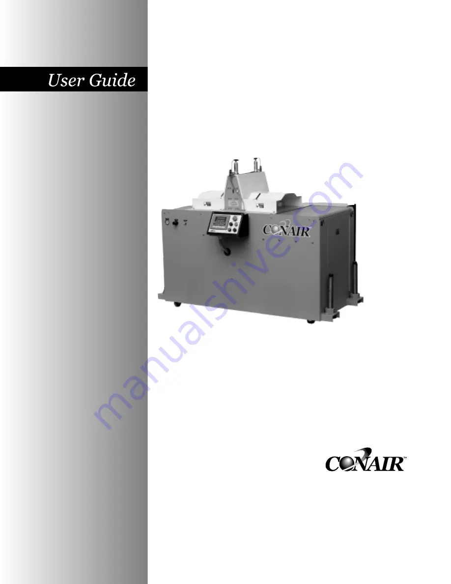
background image

Traveling Saw

Instant Access 

Parts and Service

(800) 458-1960
(814) 437-6861

www.conairnet.com

The Conair Group, Inc.
One Conair Drive
Pittsburgh, PA 15202
Phone: (412) 312-6000
Fax: (412)-312-6227

CTS Models 5, 7 and 9

UGE058/0803

Installation

Operation

Maintenance

Troubleshooting

Summary of Contents for CTS 5

Page 1: ...and Service 800 458 1960 814 437 6861 www conairnet com The Conair Group Inc One Conair Drive Pittsburgh PA 15202 Phone 412 312 6000 Fax 412 312 6227 CTS Models 5 7 and 9 UGE058 0803 Installation Ope...

Page 2: ...number s Model number s Power Specifications Amps Volts Phase Cycle DISCLAIMER The Conair Group Inc shall not be liable for errors contained in this User Guide or for incidental consequential dam ages...

Page 3: ...3 3 Positioning the CTS Saw 3 4 Connecting the Main Power Source 3 6 Installing the Encoder 3 7 Installing the Saw Blades 3 8 Preparing for Testing 3 9 Testing the Installation 3 9 OPERATION 4 1 The S...

Page 4: ...ords of Caution 6 2 Identify the Cause of a Problem 6 3 Electrical Problems 6 4 Product Quality Problems 6 5 Checking the Servo Amplifier 6 7 Checking the Encoder 6 8 APPENDIX Customer Service Informa...

Page 5: ...58 0803 CTS Saw Purpose of the User Guide 1 2 How the User Guide is organized 1 2 Your Responsibilities as a User 1 2 ATTENTION Read this so no one gets hurt 1 3 How to Use the Lockout Device 1 5 INTR...

Page 6: ...rs or could damage equipment Read and take precautions before proceeding Numbers within shaded squares indicate tasks or steps to be performed by the user A diamond indicates the equipment s response...

Page 7: ...mind You can avoid the potential hazards identified on this machine by fol lowing the procedures outlined below and elsewhere in the User Guide ATTENTION READ THIS SO NO ONE GETS HURT UGE058 0803 CTS...

Page 8: ...onductive ground wire from the incoming power supply must be connected to the chassis ground terminal inside the electri cal enclosure Improper grounding can result in severe personal injury and errat...

Page 9: ...hod of isolating machines or equipment from energy sources Your Conair product is equipped with the lockout device pictured below To use the lockout device Stop or turn off the equipment Isolate the e...

Page 10: ......

Page 11: ...2 1 UGE058 0803 CTS Saw What is the CTS Saw 2 2 Typical Applications 2 2 How the CTS Saw Works 2 3 CTS Saw Features 2 5 Specifications 2 6 Optional Equipment 2 7 DESCRIPTION...

Page 12: ...rientation is right to left saws can also be made with a left to right orientation see Specifications in this section The illustrations in this User Guide represent the standard right to left configur...

Page 13: ...he saw blade travels up and through the product 3 The saw blade returns to its down home position 4 The clamp releases the product 5 The saw table returns to its starting home position and readies for...

Page 14: ...THE CTS SAW WORKS CONTINUED Saw clamps hold the prod uct in place while the blades passes through it during the cutting cycle Cut pieces are col lected on a dump table or carried away on a conveyor E...

Page 15: ...for easy maintenance Self contained table to reduce machine footprint and enhance safety with no moving parts extending past the base Front mounted pneumatic flow controls Front mounted elec trical co...

Page 16: ...ht lbs kg Installed 575 261 825 374 1700 771 Shipping 675 306 925 420 1800 817 Voltage Total Amps 230V 3 phase 60 Hz 9 7 A 15 1 A 15 1 A 460V 3 phase 60 Hz 4 9 A 7 6 A 7 6 A 230V 3 phase 60 Hz servo 2...

Page 17: ...ut length and repeat able length accuracy Dust collector system for material particulates retention highly recommended for proper operation Left to right machine operation This options changes the mac...

Page 18: ......

Page 19: ...the Boxes 3 2 Preparing for Installation 3 3 Positioning the CTS Saw 3 4 Connecting the Main Power Source 3 6 Installing the Encoder 3 7 Installing the Saw Blades 3 8 Preparing for Testing 3 9 Testing...

Page 20: ...r tape and plastic Compare contents to the shipping papers to ensure that you have all the parts Carefully inspect all components to make sure no damage occurred during shipping Check all wire ter min...

Page 21: ...gh clearance around the saw for maintenance and servicing PREPARING FOR INSTALLATION UGE058 0803 CTS Saw INSTALLATION 3 3 1 2 WARNING Improper installation oper ation or servicing may result in equipm...

Page 22: ...cessary to allow 6 8 feet between the puller and saw Align the saw with the extrusion line Measure the centerline height of the extrudate as it exits the extrusion die Adjust all equipment on the extr...

Page 23: ...djust the pad assembly to remove the weight from the casters for operation This minimizes machine vibration during the cutting cycle Use a plumb line or laser to check for a straight line from the ext...

Page 24: ...w and the most accurate electri cal component information CONNECTING THE MAIN POWER SOURCE 3 WARNING Electrical hazard Before performing any work on this product dis connect and lock out electrical po...

Page 25: ...ler depends on your particular puller and application If the wheel rides on the puller belt make sure that its lin ear alignment is the same as the belt Place the wheel near the center of the belt to...

Page 26: ...hex nut The blade is held on with a hex nut tightened on the motor arbor shaft Based on either right to left or left to right saw operation the hex nut will be either a left hand or right hand thread...

Page 27: ...orrect phas ing The phase in your plant may be different from the Conair factory Press the saw start button Turn off the saw and vacuum Check the saw blade rotation The top of the saw blade should tur...

Page 28: ......

Page 29: ...4 Blade Height Adjustment 4 4 Upper Clamp Adjustment 4 5 Power Supply 4 5 Control Panels 4 5 Pneumatic Cylinder Operation 4 6 Electrical Operation 4 7 Machine Lubrication 4 8 System Inspection 4 8 Bla...

Page 30: ...on the cut off saw Make sure that the FRL is set for 6 65 PSI Press MANUAL CUT Adjust the TABLE FORWARD speed control to match the approximate line speed Adjust the SAW BLADE UP speed control to the...

Page 31: ...clamp pressure regulator to grasp the pro file firmly THE CONTROL FEATURES CONTINUED 13 14 NOTE The TABLE RETURN pressure must be set high enough to return the table to the start position and trig ger...

Page 32: ...and driven by a 3500 RPM arbor motor This motor is mounted on a pivot assembly which guides and secures the saw blade through the cutting process There is adjustment for how high the saw blade will e...

Page 33: ...ase as specified on the machine nameplate Connect the machine power through a fused discon nect of proper rating Make sure the power is grounded through the power cable to the plant electrical ground...

Page 34: ...w con trols mounted on the Cylinders Clockwise rotation will slow the clamp movement speed and counterclockwise rotation will increase the clamp movement speed The table and clamp pressure setting is...

Page 35: ...er this hap pens the saw pivot assembly will raise the blade up through the table slot until it reaches its up limit switch Upon reaching this switch the saw pivot will immediately return down through...

Page 36: ...he saw motor carriages travel on will after time begin to wear from the constant con tact with the cam rollers They should be visually inspected for wear and replaced as necessary Saw Track Rollers Th...

Page 37: ...ion Remove the hex nut using the spanner wrench provided to hold the blade shaft The saw blades will be removable at this time BLADE REPLACEMENT UGE058 0803 CTS Saw OPERATION 4 9 IMPORTANT Always note...

Page 38: ...ate of chip removal is dependent on the type and ability of the customer supplied removal system or Conair s optional vacuum system CHIP COLLECTION SHROUDS AND BLOWER CONNECTION CTS Saw UGE058 0803 4...

Page 39: ...GE058 0803 CTS Saw Maintenance Features 5 2 Warnings and Cautions 5 2 Maintenance Overview 5 4 Preventative Maintenance Schedule 5 4 Checking the Blades 5 6 Checking Electrical Connections 5 7 MAINTEN...

Page 40: ...annual every 6 months schedule Use this maintenance schedule as a guide You may need to shorten the time of the maintenance schedule depending on how often you use the saw and the types of material f...

Page 41: ...electrical power sources to prevent injury from unexpect ed energization or start up A lockable device has been provided to isolate this product from potentially hazardous electricity DANGER Sharp bl...

Page 42: ...Blade Replacement Inspecting the blade mounting hardware The blade securing bolt should use both a lock washer and flat washer and be tightened enough to fully com press the lock washer Replace the h...

Page 43: ...smooth downward return Check that the adjustable mufflers on the clamp cylinder are set so that the clamp operates quickly a slow cycle on the clamp down will cause inaccu rate cuts in length Check th...

Page 44: ...pending on the material being cut cut rate blade speed and blade material and thickness Check blades regularly for sharpness as well as scratches nicks burrs and material buildup Clean sharpen or repl...

Page 45: ...y from unexpected ener gization or start up A lockable device has been provided to isolate this product from potentially hazardous electricity WARNING Improper installation oper ation or servicing may...

Page 46: ...ver heated wires Have a qualified electrician make any necessary repairs or replacements Close the electrical enclosure door Inspect the exterior power cords Cords should not be crimped exposed or rub...

Page 47: ...Saw Before Beginning 6 2 A Few Words of Caution 6 2 Identifying the Cause of a Problem 6 3 Electrical Problems 6 4 Product Quality Problems 6 5 Checking the Servo Amplifiers 6 7 Checking the Encoder...

Page 48: ...with the saw BEFORE BEGINNING CTS Saw UGE058 0803 6 2 TROUBLESHOOTING A FEW WORDS OF CAUTION WARNING Improper installation oper ation or servicing may result in equipment damage or personal injury Thi...

Page 49: ...d product This section does not provide solutions to problems originating with other equipment on the extrusion line Additional troubleshooting help can be found in the manufac turer s manuals include...

Page 50: ...and when information input is not executed properly Symptom Saw will not start Saw blade runs backwards Possible cause The E stop button is depressed Motor overload tripped Disconnect in the off posi...

Page 51: ...olution Re align the product guides Insure that the rear guide is square with the saw blade and tighten Adjust the front guide accordingly allowing enough clearance for smooth product passage Adjust s...

Page 52: ...ller ways dirty Rodless cylinder problem Solenoid problem Low air pressure Solution Check encode or input device Check puller for drive consis tencies or any belt to product slippage Check cut length...

Page 53: ...an be seen through the viewing window on the electrical enclosure This display shows amplifier status and error mes sages Refer to the supplier s documentation included with this User Guide NOTE Make...

Page 54: ...replace Check the connector that attaches the cable to the encoder Internal wiring may be shorted out if this connector is not handled properly Check the encoder itself There should be no play in the...

Page 55: ...owing checklist before calling Conair Make sure you have all model serial and parts list numbers for your particular equipment Service personnel will need this information to assist you Make sure powe...

Page 56: ...l exercise one of the following options Inspect the equipment and perform alterations or adjust ments to satisfy performance claims Charges for such inspections and corrections will be waived unless f...

Page 57: ...rane panel consisting of 22 keys and a large 2 line x 20 back lit LCD screen Soft Keys Soft keys these are the three keys directly under the display All three have a triangle on them Occasionally page...

Page 58: ...n universal symbols and text The fixed function keys are Raise Lower Next Prev previous Enter Delete Exit Menu and Mute These functions are described in the Function keys Fixed Functions section of th...

Page 59: ...Total Reset Page 8 Homing Page 9 Home Already Page 10 Menu Area Password Access Page 11 Maintenance Area Encoder Direction Page 12 Preventive Maintenance Area Power On Time Page 13 Machine Cycles Tabl...

Page 60: ...blems with communications this screen will remain on longer than a couple of seconds If there are no communication problems the Conair Servo Traveling Saw program will begin to run The following messa...

Page 61: ...ced If a negative symbol is shown to the left of the count value the encoder signal is reversed i e rotating in the wrong direction The Saw will not function while the encoder is going negative It is...

Page 62: ...he right is a soft key labeled Reset Pressing this key will zero the counter Exit Softkey Under the counter in the center is a soft key labeled Exit Pressing this key will return the display to the Ma...

Page 63: ...ng the key will freeze the preset at the last value Lower will decrease the preset by 0 01 The key can be pressed once for each 0 01 decrement required or held down to scroll down Releasing the key wi...

Page 64: ...Home Seek If the saw table has been stopped away from the home location and the power to the machine switched off upon reapplying power the first motion will be a home seek Pressing the start push bu...

Page 65: ...e home sensor After this motion is similar to the previous description After a successful home has been completed if the saw is stopped and the power to the machine is left on the table position is st...

Page 66: ...scheduling purposes Maint Softkey Located under the word Maint is the Maintenance soft key The Maintenance area is password protected This area should only be accessed by qualified personal After pres...

Page 67: ...f the display is the status text INCORRECT CORRECT for the encoder direction Exit or Prev Pressing Exit or Prev will return the display to the Maint Area screen Change Softkey With the machine stopped...

Page 68: ...rea screen selects the power on time screen The Power On time screen displays the total time in hours that the machine has had the power switched on This information could be used for scheduling preve...

Page 69: ...an not be reset Exit or Prev Pressing Exit Prev or the Softkey under the word Exit returns the display to the P M area screen Table Softkey Pressing the soft key located under the word Table on the Ma...

Page 70: ...last value Lower will decrease the preset by 10 00 ipm The key can be pressed once for each 10 00 ipm decrement required or held down to scroll down Releasing the key will freeze the preset at the las...

Page 71: ...ill freeze the preset at the last value Lower will decrease the preset by 0 01 The key can be pressed once for each 0 01decrement required or held down to scroll down Releasing the key will freeze the...

Page 72: ...to your machine ERROR MESSAGE If a cut has not completed within a safe amount of table travel this message is displayed The message will remain until any key is pressed The saw will continue to attem...

Page 73: ...678001 6 V Roller Steal 5 29031102 2 Bearing Flange 2 Bolt 6 26676701 1 Motor Saw Arbor 7 26677901 4 Roller Adjustable Height 8 29037407 1 Cylinder 6 Stroke Motor 9 26677301 1 Belt Plastic Conveyor 28...

Page 74: ...iming 24 29053322000850 1 Belt Timing 25 26671748 2 Prox Inductive 26 26671810 2 Prox Cable 27 26676901 1 Switch Magnetic 28 26667660101 2 Solenoid Valve 29 315 165 1012 4 Exhaust 30 315 167 3007 1 Va...

Page 75: ...2N C 45 27500109 1 Transformer 250VA 240 480v 46 20801476 1 Receptacle Amphenol 4 Pin 47 20801459 1 Connector Amphenol 10 Pin 48 26671601 2 Relay 49 26671602 2 Relay 50 1605 30000 1 Relay Time 51 1608...

Reviews: